
Instruction manual

Appendix 1. Outline Dimension Drawings
A1 - 15
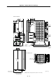
Appendix 1-1-3 SJ-VS Series
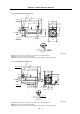
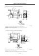
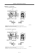
• SJ-VS7.5-03ZM with standard flange
φ
2
5
0
M16
M16
198
A
B
32
A
5
5□208
160
φ
2
7
5
φ
2
1
5
□204
504
340
5
13
47
405.5
453
210 230.5
80
4-φ15
B
φ44
3
5
°
Cooling fan Exhaust ai
r
Cooling air inlet
Terminal box
M16 Left screw
M16 Right scre
w
[Unit: mm]
(Note 1) Provide a clearance of 30mm or more between the cooling fan and wall.
(Note 2) The shaft can also be mounted upward.
(Note 3) If the suspension bolts are removed during operation, plug the screw holes with bolts.
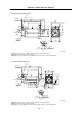
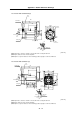
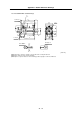
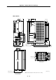
• SJ-VS22-06ZM with standard flange
φ
3
0
0
M16
M16
238
A
B
32
A
5
5□262
190
φ
2
7
5
φ
2
6
5
□250
545
351
5
20
65
411.5
479
210 241.5
110
4-φ15
B
φ44
3
5
°
Cooling fan Exhaust ai
r
Cooling air inlet
Terminal box
M16 Left scre
w
M16 Right screw
[Unit: mm]
(Note 1) Provide a clearance of 30mm or more between the cooling fan and wall.
(Note 2) The shaft can also be mounted upward.
(Note 3) If the suspension bolts are removed during operation, plug the screw holes with bolts.