
Instruction manual


Appendix 1. Outline Dimension Drawings
A1 - 5
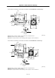
Appendix 1-1-2 SJ-V Series
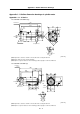
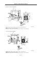
• SJ-V2.2-01, SJ-V3.7-02ZM with standard flange
168
2-M6
8
45
16
8
4-φ12
□174
□176
φ35
5 5
φ
1
9
0
60
12
548
φ
2
2
0
φ
1
8
5
A
A
130
265
300
360
φ28j6
A
A
Terminal box
Exhaust air
Cooling fan
Cooling air inlet
Screw
Cross section
A-A
Flange
[Unit: mm]
(Note 1) Provide a clearance of 30mm or more between the cooling fan and wall.
(Note 2) The shaft can also be mounted upward.
(Note 3) If the suspension bolts are removed during operation, plug the screw holes with bolts.
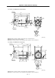
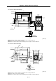
• SJ-V2.2-01, SJ-V3.7-02ZM with standard legs
168
8
φ28j6
16
2-M6
176
60
45 8
56
75
105 41
35
180
70 70
4-φ10
A
A
265
130
300
360
φ35
55
A
A
Exhaust ai
r
Terminal box
Cooling fan
Screw
Cross section
A-A
Cooling
air inlet
[Unit: mm]
(Note 1) Provide a clearance of 30mm or more between the cooling fan and wall.
(Note 2) The shaft can also be mounted upward.
(Note 3) If the suspension bolts are removed during operation, plug the screw holes with bolts.