
Instruction manual


Appendix 1. Outline Dimension Drawings
A1 - 4
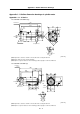
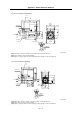
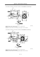
• SJ-45BP, SJ-22XW8 with standard flange
733
792
932
140
30
5
73
15
140
110
A
A
77 378
5
8
1
3
5
°
φ
4
2
5
φ
4
0
0
60m6
18
A
A
4-φ19
φ425
φ63
278
Terminal box
Exhaust ai
r
Cooling fan
Cooling air inlet
Cross section
A-A
[Unit: mm]
(Note 1) Provide a clearance of 30mm or more between the cooling fan and wall.
(Note 2) The shaft can also be mounted upward.
(Note 3) If the suspension bolts are removed during operation, plug the screw holes with bolts.
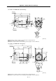
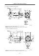
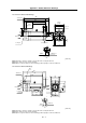
• SJ-45BP, SJ-22XW8 with standard legs
4-φ19
159 159
400
85
6 6380
15110
A
A
133152.5152.5
385
447.5
506.5 272.5 140
425.5
932
18
60m6
AA
φ63
278
Terminal box
Exhaust air
Cooling fan
Cooling
air inlet
Cross section
A-A
[Unit: mm]
(Note 1) Provide a clearance of 30mm or more between the cooling fan and wall.
(Note 2) If the suspension bolts are removed during operation, plug the screw holes with bolts.