
Instruction manual

4. Dedicated Options
4 - 3
4-1-1 Magnetic sensor
Prepare the magnetic sensor parts with the following types. When purchasing independently, always
prepare with the required configuration part types.
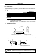
(1) Type
Independent type
Type Type
Tolerable
speed [r/min]
Drive unit Sensor Magnet
Standard MAGSENSOR BKO-C1810H01-3 0 to 6000 H01 H02 H03
High-speed standard MAGSENSOR BKO-C1730H01.2.6 0 to 12000 H01 H02 H06
High-speed small MAGSENSOR BKO-C1730H01.2.9 0 to 12000 H01 H02 H09
MAGSENSOR BKO-C1730H01.2.41 0 to 25000 H01 H02 H41
MAGSENSOR BKO-C1730H01.2.42 0 to 25000 H01 H02 H42
MAGSENSOR BKO-C1730H01.2.43 0 to 30000 H01 H02 H43
High-speed ring
MAGSENSOR BKO-C1730H01.2.44 0 to 30000 H01 H02 H44
(Note) When preparing with independent types, replace the section following the H in the
prepared type with the independent type.
Example: When preparing only the standard magnetic sensor's sensor section, the
type will be MAGSENSOR BKO-C1810H02.
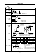
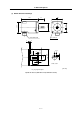
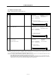
(2) Outline dimension drawing:
z Drive unit H01
2-ø5.5 hole
Connector (sensor side)
For BKO-C1810H01, R04-R08F is used.
For BKO-C1730H01, TRC116-21A10-7F is used.
Connector (controller cable side)
Unit side (TRC116-21A10-7M)
Cable side (TRC116-12A100-7F10.5)
25
[Unit: mm]
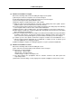
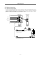
z Sensor H02
32
18
25
14
1
5.5
Cable length 500
+100
-0
Connector
For BKO-C1810H02, R04-R-8M is used.
For BKO-C1730H02, TRC116-12A10-7M is used.
ø6
30
5
5
25
17.5
20
Reference
notch
[Unit: mm]
CAUTION
When using the magnetic sensor, orientation control cannot be carried out with a
machine having a gear ratio between the spindle motor and spindle exceeding
1:31.