
Instruction manual


2. Specifications
2 - 24
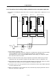
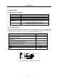
2-3-3 Precautions when installing multiple spindle drive units to one power supply unit
The methods for installing two spindle drive units to one power supply unit are explained here as an
example.
C
N
10
11
12
8A
9A
C
N
4
C
N
4
C
N
9
C
N
4
C
N
10
11
12
8A
9A
L+, L-
L11, L21
MC1
NC(PC)
MDS-C1-SPA (No.1) MDS-C1-CV MDS-C1-SPA (No.2)
MC
NFB1
2
00VAC
A
C reactor
(B-AL)
Contactor
L1, L2, L3
(1) Connecting C1-CV and C1-SPA
Connect C1-CV CN4 and C1-SPA (No. 1) CN4 to C1-CV CN9 and C1-SPA (No.2) CN4. If C1-SPA is
connected with three or more axes, leave CN4 for C1-SPA (No. 3) and following open.
Note that the C1-CV can be controlled (READY ON/OFF, alarm display, etc.) only by the spindle
drive unit connected to C1-CV CN4.
(2) Make sure that the machine ready complete input turns ON and OFF simultaneously for all the
spindle drive units. Do not allow the signal to turn ON and OFF for only one spindle drive unit.
(3) When turning the machine ready complete input OFF during an emergency stop, always have all the
spindle drive units output the zero speed signal before turning the signal OFF.
(4) If an alarm occurs in one of the spindle drive units, turn OFF the machine ready complete input OFF
for all the spindle drive units.
(5) When connecting three or more spindle drive units, install the large-capacity spindle drive units on
both sides of the power supply unit.