
Instruction manual

2. Specifications
2 - 21
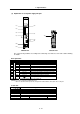
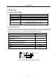
(2) Explanation of each power supply unit part
<3>
<11>
<2>
<1>
<5>
<4>
<7>
<8>
<10>
<9>
<6>
MDS-C1-CV Bottom view
The connector layout differs according to the unit being used. Refer to each unit's outline drawing
for details.
Each part name
Name Description
<1> LED --- Power supply status indication LED
<2> SW1 --- Power supply setting switch
<3> CN4 --- Spindle communication connector (master)
<4> CN9 --- Spindle communication connector (slave)
<5> --- CHARGE LAMP TE2 output charging/discharging circuit indication LED
<6>
Control circuit
CN23 --- External emergency stop input connector
<7> TE2 L+, L– Converter voltage output terminal (DC output)
<8> L11, L21 Control power input terminal (single-phase AC input)
<9>
TE3
MC1 External contactor control terminal
<10> TE1 L1, L2, L3 Power input terminal (3-phase AC input)
<11>
Main circuit
PE
Grounding terminal
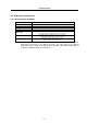
(Note1) CN23 is located at the bottom of the power supply unit.
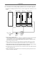
(Note2) For customer switching from MDS-A/B Series
Make sure that PE terminal position has changed from UVW terminal to the bottom of the cooling fan.
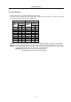
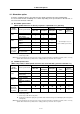
Screw size
Power supply unit MDS-C1-CV-
Type 37 to 75 110 150 to 185 220 to 370
Unit width (mm) 60 90 120 150
<7> L+, L– M6 x 16
<8> L11, L21 M4 x 10
<9> MC1 M4 x 10
<10> L1, L2, L3 M4 x 10 M5 x 12 M8 x 14
<11>
M4 x 8 M5 x 8 M8 x 14