
Instruction manual


2. Specifications
2 - 20
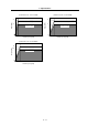
2-2-6 Explanation of each part
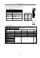
(1) Explanation of each spindle drive unit part
<8>
<3>
<4>
<7>
<14>
<6>
<5>
<1>
<2>
<11>
<12>
<13>
<9>
<10>
MDS-C1-SPA
The connector layout differs according to the unit being used. Refer to each unit's outline drawing
for details.
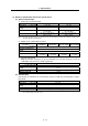
Each part name
Name Description
<1> LED --- Unit status indication LED
<2>
SW1,
PB1,
PB2,
PB3
---
SW1: Axis No. setting switch
PB1,2,3: Parameter setting button
<3> CN10 ---
General-purpose input output / DC power supply connection
connector
<4> CN11 --- Orient position shift / general-purpose output connector
<5> CN9A --- Personal computer connection / analog output connector
<6> CN4 --- Power supply communication connector
<7> CN5 --- Internal PLG encoder connection connector
<8> CN6 --- Magnetic sensor / external encoder connection connector
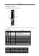
<9> CN12 --- Digital speed command / general-purpose output connector
<10>
Control circuit
CN8A --- Analog speed command / override / pulse output connector
<11> TE2 L+, L– Converter voltage input terminal (DC input)
<12> TE3 L11, L21 Control power input terminal (single-phase AC input)
<13> TE1 U, V, W Motor power output terminal (3-phase AC output)
<14>
Main circuit
PE
Grounding terminal
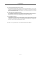
(Note1) For customer switching from MDS-A/B Series
Make sure that PE terminal position has changed from UVW terminal to the bottom of the cooling fan.
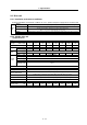
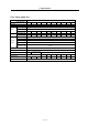
Screw size
Spindle drive unit MDS-C1-SPA-
Type 04 to 37 55 to 110,150S 150 to 185 220 to 300
Unit width (mm) 60 90 120 150
<11> L+, L– M6 x 14
<12> L11,L21 M4 x 10
<13> U, V, W M4 x 12 M5 x 12 M8 x 14
<14>
M4 x 8 M5 x 12 M8 x 14