
Instruction manual


2. Specifications
2 - 14
(3) Details on spindle drive unit function specifications
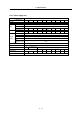
(a) Speed command input
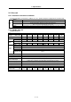
1) Analog speed command input
When using bipolar input When using unipolar input
Input voltage -10 to +10V 0 to +10V
Tolerable maximum input
voltage
-15 to +15V -15 to +15V
Input part connector, pin No.
Between CN8A-No.7 pin (SE1) and
No.8 pin (SE2)
Between CN8A-No.17 pin (OR2) and
No.18 pin (OR1)
Resolution
10V/ approx. 1940 divisions
(approx. 5.1mV)
10V/ approx. 3570 divisions
(approx. 2.8mV)
(Note 1)
Tolerable maximum input does not guarantee the speed linearity, but specifies the maximum voltage in which
the drive unit will not be damaged.
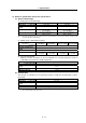
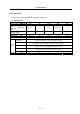
2) Digital speed command input (option)
Binary
(12bit binary)
Signed binary BCD code 3digits BCD code 2digits
Input Contact input Sink • source input available
Tolerable maximum input
voltage
26.4V
Input part connector CN12
Resolution
Motor maximum
speed/4095
Motor maximum
speed/2048
Motor maximum
speed/999
Motor maximum
speed/99
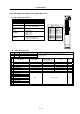
3) Speed selection input
With this function, 8 patterns of speed commands are selected using up to 3 bits in
combination. Speed can be set with a parameter.
Speed selection
Input Contact input Sink and source input available
Tolerable maximum input
voltage
26.4V
Input part connector Select maximum three of CN10 general-purpose input
Minimum setting unit 1r/min
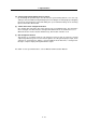
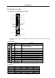
(b) Override input
This function is valid when the override input contact set with the
general-purpose input is
turned ON.
When using unipolar input
Input voltage 0 to +10V
Tolerable maximum input
voltage
-15 to +15V
Input part connector, pin No. Between CN8A-No.17 pin (OR2) and No.18 pin (OR1)
Resolution 10V/ approx. 3570 divisions (approx. 2.8mV)
(Note 1)
When using unipolar analog input, digital speed command input and speed selection for the speed command,
the override function cannot be used.