
Instruction manual

Appendix 7. EMC Installation Guidelines
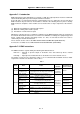
A7 - 7
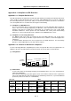
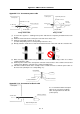
Appendix 7-5-5 Spindle motor power cable
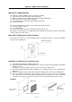
Control panel
To drive unit
Earth with
P or U clip
Terminal
box
Shield cable
Spindle moto
r
Control panel
To drive unit
Conduit
connecto
r
Conduit
Cabtyre cable
Terminal
box
Earth with paint mask
Using shield cable Using conduit
(1) Use four wires (3-phase + earthing) for the power cable that are completely shielded and free from
breaks.
(2) Earth the shield in the same manner as the servomotor power cable.
(3) When not using a shield cable for the power cable, use a conventional cabtyre cable. Use a metal
conduit outside the cable.
(4) Earth the power cable on the control panel side at the contact surface of the conduit connector and
control panel side wall in the same manner as the servomotor power cable. (Mask the side wall of
the control panel with paint.)
(5) Earth at the conduit connector section in the same manner as the servomotor power cable.
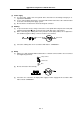
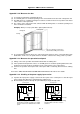
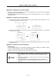
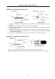
Appendix 7-5-6 Spindle motor feedback cable
Control panel
To drive unit
Terminal box
Batch shield pair cable
Clamp the shield, and connect to
the connector case.
Spindle side connector
(State with the cover removed)
(1) Use a conventional batch shield pair cable for the spindle motor feedback cable.
Note) A shield for the spindle motor feedback cable is not "FG", and therefore do not ground it.