
Instruction manual


Appendix 5. Explanation of Small Capacity Spindle Drive Unit Specifications
A5 - 5
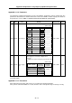
Appendix 5-1-5 Heating value
Heating value
MDS-B-SPA-
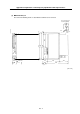
Inside panel Outside panel
04
30 -
075
40 -
15
50 -
22
27 43
37
29 51
(Note 1) The heating value is the value at the continuous rated output.
Appendix 5-1-6 Selecting the wire size
(1) Recommended wire size for spindle motor output wire
Regardless of the motor type, select the wire size based on the spindle drive unit capacity as shown
below.
MDS-B-SPA- IV wire (60
o
C) HIV wire (75
o
C)
04
075
2mm
2
15
22
37
3.5mm
2
2mm
2
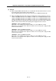
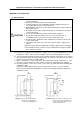
(Note 1) The wire sizes recommended in (1) above are selected under the conditions that the ambient temperature is 30°C
and three tubes are wired.
During actual use, select the wire based on the above reference while considering the ambient temperature, wire
material, and wiring state.
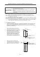
(Note 2) To suppress the L+ and L– link bar size to the minimum required for each unit, select as shown below based on the
total output current of the motor to be load.
First, obtain the motor output current of each drive unit based on the drive unit capacity.
Spindle motor (Decide according to the drive unit capacity )
Unit capacity MDS-B-SPA□-
04 075 15 22 37
Motor output current (A)
4 6 10 17 25
(2) L11, L21
Regardless of the spindle drive unit capacities, use the wire size of IV2mm
2
or more.
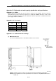
Appendix 5-1-7 Drive unit connection screw size
Terminal name Screw size
U,V,W,G
M4
L+,L-
M6
L11,L21
M4