
Instruction manual


Appendix 5. Explanation of Small Capacity Spindle Drive Unit Specifications
A5 - 3
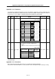
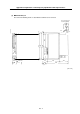
(2) MDS-B-SPA-22, 37
The front view drawing shows a state with the terminal cover removed.
52
2-ø6 hole
60
30
Wiring
space
Terminal cove
r
180
10
15
195
350
380
360
10
15
20
70
L+
L11
L21
U V W
320
120
FAN
360
342
9
9
2-M5 screw
Square hole
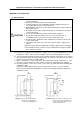
Panel mounting hole
machining drawing
L-
[Unit : mm]