
Instruction manual


Appendix 4. Explanation of Large Capacity Spindle Unit Specifications
A4 - 12
Appendix 4-1-11 Restrictions
(1) Mounting
Always mount the MDS-B-SPA-370,450, 550 on the left of the power supply unit.
When using MDS-B-CVE-450, 550, always use the enclosed link bar to connect L+ and L- on the
MDS-B-SP-370, 450, 550.
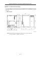
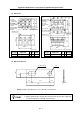
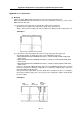
(a) Layout when connecting only one spindle drive unit to power supply unit.
Mount the power supply on the right and the spindle drive unit on the left.
Always cut the panel according to the panel cut dimension drawings shown in Appendix 5-1-5.
<Example 1>
MDS-B-SPA-450 MDS-B-CVE-450
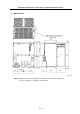
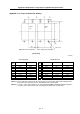
(b) Layout when connecting multiple drive units to a large capacity power supply unit
The following number of spindle drive units can be additionally connected.
• When MDS-B-CVE-450 and MDS-B-SPA-370 are combined, 9kW (=45kW–37kW+1kW)
worth of units.
• When MDS-B-CVE-550 and MDS-B-SPA-450 are combined, 11kW (=55kW–45kW+1kW)
worth of units.
• When MDS-B-CVE-450 and MDS-B-SPA-370 are combined, 19kW (=55kW–37kW+1kW)
worth of units.
In this case, arrange the MDS-B-SPA-370, 450 to the left of MDS-B-CVE-450, 550 as shown in
the panel cut dimension drawings in Appendix 5-1-5. Mount the additional drive units to the
right of the MDS-B-CVE-450, 550.
If the spindle motor output differs from the spindle drive unit output, the above, excluding the
layout, may not always apply. (This is because the power supply unit's output is determined by
the motor output.)
<Example 2>
MDS-
B-SPA-370
MDS-
B-CVE-450
MDS-
B-SPA-37
(2-axis)