
Instruction manual


Appendix 4. Explanation of Large Capacity Spindle Unit Specifications
A4 - 11
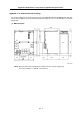
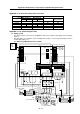
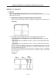
(b) When using MDS-B-CVE-450, 550
L1 L2 L3
U V W
L+
L-
L+
L-
Contactor
PLG
MAG
ENC
Spindle motor
A
C reactor
L11
L21
NC
Uppe
r
step
Lower
step
U V W
Blower
NFB
For motor blower
L11 L21
L11 L12 MC1
L21 L22 MC2
CN4
CN9
3
φ
200VAC 50Hz
3
φ
200 to 220VAC 60Hz
NFB
B-AL
A
lways use the link
bar enclosed with
B-CVE.
PLG
MAG
Spindle motor
Blower
NFB
For motor blower
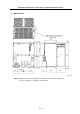
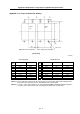
CN11
CN10 CN9A CN5 CN12
CN8A
CN6 CN4
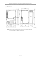
CN11
CN10
CN9
A
CN5
CN12
CN8
A
CN6 CN4
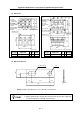
MDS-B-SPA(H)-370 to 550 MDS-B-CVE-450/550
MDS-B-SPA(H)
-040 to 37
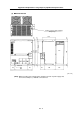
MDS-C1-SPA(H)
-55 to 300
(Note 1) Connect the L11, L21 and MC1 external connections without removing the conductors
connected between L21 and L22, L22 and MC2, and L11 and L12 of the MDS-B-CVE-450,
550.
(L12, L22 and MC2 are for special specifications, and normally, the external connection is not
required.)
(Note 2) Always connect the contactor to MC1 so that it can be controlled with the drive unit's internal
signal. The power supply unit could be damaged if the contactor is turned ON and OFF with a
separate user-prepared sequence.
(Note 3) One end of the contactor coil is connected to the MC1 terminal and the other end is
connected to the power supply. The phase on the side connected to the power supply must
be different from the phase connected to the power supply unit's L21.