
Instruction manual


Appendix 4. Explanation of Large Capacity Spindle Unit Specifications
A4 - 10
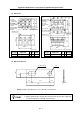
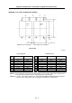
Appendix 4-1-9 Drive unit connection screw size
Power supply unit Spindle drive unit
MDS-B-CVE-450 MDS-B-CVE-550
Type
Left Right Left Right
MDS-B-SPA-370
MDS-B-SPA-450
MDS-B-SPA-550
L1, L2, L3 M8 M10 – –
U, V, W – – M8 M10
L+, L– M10 M6 M10 M6 M10 M10
L11, L21 M4 M4 M4 M4
MC1 M4 M4 – –
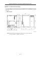
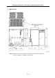
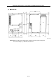
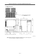
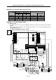
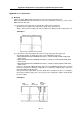
Appendix 4-1-10 Connecting each unit
(1) Wiring system
The wiring system is the same as the MDS-C1-SPA Series. (Refer to the wiring system example
below.)
Note that there are restrictions to the mounting and selection, so refer to the Restrictions given in
Section Appendix 5-1-11.
(a) When using MDS-C1-CV-370 or smaller
3
φ
200VAC 50Hz
3
φ
200 to 220VAC 60Hz
L1 L2 L3
U V W
L11 L21
UV W
A
C reactor
Contactor
B-AL
MC
L11
L21
MC1
L11
L21
L+
L-
L+
L-
L+
NC
PC
DIO
MDS-B-SPA(H)-370 to 550
MDS-C1-CV
-260 to 370
MDS-B-SPA(H)
-040 to 37
MDS-C1-SPA(H)
-55 to 300
CN4 CN9
NFB
NFB
For motor blower
L-
PLG
MAG
ENC
Spindle motor
Blower
CN11
CN10
CN9A
CN5
CN12
CN8A
CN6 CN4
ENC
PLG
MAG
Spindle motor
Blower
NFB
For motor blower
CN11
CN10
CN9A
CN5
CN12
CN8A
CN6 CN4