
Instruction manual


Appendix 4. Explanation of Large Capacity Spindle Unit Specifications
A4 - 8
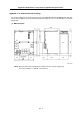
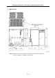
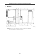
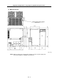
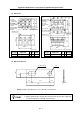
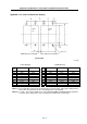
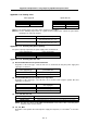
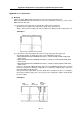
Appendix 4-1-5 Panel cut dimension drawing
Unit [mm]
Power supply unit Spindle drive unit
Sym-
bol
MDS-B-CVE-450 MDS-B-CVE-550
Sym-
bol
MDS-B-SPA-370 MDS-B-SPA-450 MDS-B-SPA-550
H 360±0.3 360±0.3 H 360±0.3 360±0.3 360±0.3
W 222±1 282±1 W 222±1 282±1 282±1
H1 341±1 341±1 H1 341±1 341±1 341±1
H2 10±0.5 10±0.5 H2 10±0.5 10±0.5 10±0.5
W1 120±0.3 180±0.3 W1 – – –
W2 – – W2 120±0.3 180±0.3 180±0.3
W3 51±0.5 51±0.5 W3 51±0.5 51±0.5 51±0.5
W4 18±0.5 18±0.5 W4 – – –
W5 120±0.5 120±0.5 W5 – – –
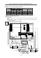
(Note 1) The spindle drive unit must be mounted to the left of the power supply unit looking from the
front of the unit. The panel must be cut taking this into consideration.
(Note 2) L+ and L– connection conductors are enclosed with the MDS-B-CVE-450 and 550 capacities,
so provide space between the units according to the dimensions shown above.
Square
hole
Square
hole
8-M5 screw
(Front view)
Spindle drive unit mounting side
Power supply unit mounting side