
Instruction manual


Appendix 4. Explanation of Large Capacity Spindle Unit Specifications
A4 - 7
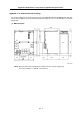
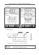
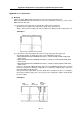
(5) AC reactor
D
D
3
±1
1) 45kW
(for wire
connection)
6-M6 screw
M5 screw
FG connection
position
Terminal cover
(with grounding mark)
PE connection
position
70
±1
4-8×15 slot
(mounting slot)
MAIN
L11
L12
L31
L32
L21
L22
DRIVE
215
±2.5
175
145
[Unit : mm]
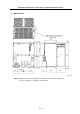
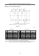
2) 55kW
(240)
D
3
±1.5
200
±1.5
MAIN
L11
L12
L31
L32
L21
L22
DRIVE
220
±2.5
190
D
±2.5
6-M10 screw
(for wire
connection)
M5 screw
FG connection
position
Terminal cover
PE connection
position
(with grounding
mark)
4-10×15 slot
(mounting slot)
[Unit : mm]
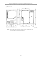
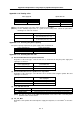
ACL type
Compatible power
supply unit
D
3
D Weight
ACL type
Compatible power
supply unit
D
3
D Weight
B-AL-45K MDS-B-CVE-450 120 160 12.8kg B-AL-55K MDS-B-CVE-550 200 320 10.0kg
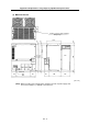
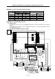
(6) DC connection bar
57.5
89
12 x 24 long hole
φ
12
14.5
(17)
3
(25)
12.5
(Note) This DC connection bar is a set of two DC connection bars.
POINT
1. These DC connection bars are accessories.
2. Always install a large capacity drive unit in the left side of power supply unit,
and connect TE2(L+,L-) with DC connection bar.