
Instruction manual


Appendix 4. Explanation of Large Capacity Spindle Unit Specifications
A4 - 4
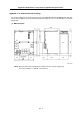
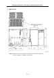
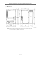
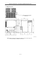
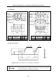
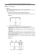
(2) MDS-B-CVE-550
340
4-ø6 hole
20
360
380
344
10
18
20
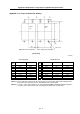
L+
L–
L1
60
60
300
180
180
63
146
120
Fin
L+
L–
A
IR
FLOW
10
18
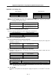
L2
L3
L11 L12
MC1
L21 L22
MC2
2-M10 screw for I-bolt mounting
178.5
64
Only on top
[Unit : mm]
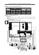
(Note) Always install a large capacity drive unit in the left side of power supply unit,
and connect TE2(L+,L-) with DC connection bar.