MELDAS is a registered trademark of Mitsubishi Electric Corporation. Other company and product names that appear in this manual are trademarks or registered trademarks of their respective companies.
Introduction Thank you for selecting the Mitsubishi numerical control unit. This instruction manual describes the handling and caution points for using this AC servo/spindle. Incorrect handling may lead to unforeseen accidents, so always read this instruction manual thoroughly to ensure correct usage. Make sure that this instruction manual is delivered to the end user. Always store this manual in a safe place. All specifications for the MDS-C1-SPA Series are described in this manual.
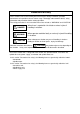
Precautions for safety Please read this manual and auxiliary documents before starting installation, operation, maintenance or inspection to ensure correct usage. Thoroughly understand the device, safety information and precautions before starting operation. The safety precautions in this instruction manual are ranked as "WARNING" and "CAUTION". DANGER WARNING CAUTION When there is a potential risk of fatal or serious injuries if handling is mistaken.
WARNING 1. Electric shock prevention Do not open the front cover while the power is ON or during operation. Failure to observe this could lead to electric shocks. Do not operate the unit with the front cover removed. The high voltage terminals and charged sections will be exposed, and can cause electric shocks. Do not remove the front cover even when the power is OFF unless carrying out wiring work or periodic inspections. The inside of the servo drive units is charged, and can cause electric shocks.
CAUTION 3. Various precautions Observe the following precautions. Incorrect handling of the unit could lead to faults, injuries and electric shocks, etc. (1) Transportation and installation Correctly transport the product according to its weight. Use the servomotor's hanging bolts only when transporting the servomotor. Do not transport the servomotor when it is installed on the machine. Do not stack the products above the tolerable number.
CAUTION Store and use the units under the following environment conditions.
CAUTION (2) Wiring Correctly and securely perform the wiring. Failure to do so could lead to runaway of the servomotor. Do not install a condensing capacitor, surge absorber or radio noise filter on the output side of the servo drive unit. Correctly connect the output side (terminals U, V, W). Failure to do so could lead to abnormal operation of the servomotor. Do not directly connect a commercial power supply to the servomotor. Failure to observe this could result in a fault.
CAUTION (3) Trial operation and adjustment Check and adjust each program and parameter before starting operation. Failure to do so could lead to unforeseen operation of the machine. Do not make remarkable adjustments and changes as the operation could become unstable. (4) Usage methods Install an external emergency stop circuit so that the operation can be stopped and power shut off immediately.
CAUTION (5) Troubleshooting If a hazardous situation is predicted during power failure or product trouble, use a servomotor with magnetic brakes or install an external brake mechanism. Use a double circuit configuration that allows the operation circuit for the magnetic brakes to be operated even by the external emergency stop signal. Shut off with the servomotor brake control output. Servomotor MBR Shut off with NC brake control PLC output.
CONTENTS 1. Introduction 1-1 Spindle drive system configuration................................................................................................... 1-2 1-1-1 System configuration ................................................................................................................. 1-2 1-1-2 Unit outline type ......................................................................................................................... 1-3 1-2 Explanation of type ..........................
Appendix 1. Outline Dimension Drawings Appendix 1-1 Outline dimension drawings of spindle motor.................................................................A1-2 Appendix 1-1-1 SJ Series..................................................................................................................A1-2 Appendix 1-1-2 SJ-V Series..............................................................................................................A1-5 Appendix 1-1-3 SJ-VS Series ...................................
Appendix 7. EMC Installation Guidelines Appendix 7-1 Introduction .....................................................................................................................A7-2 Appendix 7-2 EMC instructions ............................................................................................................A7-2 Appendix 7-3 EMC measures ...............................................................................................................
1. Introduction 1-1 Spindle drive system configuration .................................................................................................... 1-2 1-1-1 System configuration................................................................................................................... 1-2 1-1-2 Unit outline type........................................................................................................................... 1-3 1-2 Explanation of type................................
1.
1.
1. Introduction 1-2 Explanation of type 1-2-1 Spindle motor type MITSUBISHI AC SPINDLE MOTOR SJ-V5. 5-01 TYPE SI CONT 4 POLE 3 PHASES kW r/min A(~) max WIND CONNECT 3.7 1500-6000 25 P OW ER FAC TOR 17 MOTOR INPUT(~) 137 162 V 2.8 S2 8000 30 min S3 50 % A(~) max U 82 % kW r/min 5.5 1500-6000 33 AMP INPUT(~) 200-230V 50/60Hz 4.1 8000 23 INSULATION CLASS F AMB TEMP. 0-40ºC SERIAL DATE FRAME D90F WEIGHT 49 kg IEC 34-1 1994 IP 44 SPEC No.
1. Introduction 1-2-2 Spindle drive unit type MITSUBISHI Motor type SERVO DRIVE UNIT MDS-C1-SPA-55 TYPE POWER 5.5kW INPUT 20A DC270-311V 0.2A 1PH 200/200-230V 50/60Hz OUTPUT 18A 3PH 155V 0-240Hz MANUAL# IB-1500148 S/W BNDXXXXXXXXX H/W VER. * SERIAL# XXXXXXXXXXX DATE 00/01 MITSUBISHI ELECTRIC CORPORATION JAPAN Rated input Rated output Current state Serial No.
1. Introduction 1-2-3 Power supply unit type POWER SUPPLY UNIT MDS-C1-CV-150 TYPE POWER 15kW INPUT 49A 3PH 200/200-230V 50/60Hz 0.2A 1PH 200/200-230V 50/60Hz OUTPUT 58A DC270-311V 3040 DIN VDE0160 MANUAL# BNP-C3000 MITSUBISHI Motor type Rated input Rated output Current state Serial No. S/W BND538W000A1 H/W VER.
1. Introduction 1-2-4 AC reactor type Type B-AL-7.5K Nameplate Top surface of AC reactor B-AL- (1) AC reactor Motor Capatype city (kW) B-AL- Compatible power supply unit MDS-C1-CV-37 7.5K 7.5 MDS-C1-CV-55 MDS-C1-CV-75 11K 18.5K 11 18.
2. Specifications 2-1 Spindle motor ..................................................................................................................................... 2-2 2-1-1 Specifications .............................................................................................................................. 2-2 2-1-2 Output characteristics.................................................................................................................. 2-7 2-2 Drive unit ........................
2. Specifications 2-1 Spindle motor 2-1-1 Specifications Base rotation speed 1500r/min Series Spindle motor type SJ-V Compatible spindle drive unit type MDS-B/C1Continuous rating [kW] Output 30-minute rating capacity 50%ED rating [kW] Base speed [r/min] Maximum speed [r/min] Frame No.
2. Specifications Large capacity series Spindle motor type SJ30A Compatible spindle drive unit type MDS-BContinuous rating [kW] Output 30-minute rating capacity 50%ED rating [kW] Base speed [r/min] Maximum speed [r/min] Frame No.
2. Specifications Wide range constant output series Wide range (1:8) constant output series Spindle motor type SJ-V 11-01 Compatible spindle drive unit type MDS-C1Continuous rating [kW] Output capacity 30-minute rating 50%ED rating [kW] Base speed [r/min] Maximum speed Frame No. Continuous rated torque GD2 Inertia Tolerable radial load [r/min] Cooling fan Environment [N·m] [kg·m2] [kg·m2] [N] SPA-110 SJ- 15-03 18.5-03 22-05 22XW5 22XW8 SPA-185 SPA-220 SPA-260 SPA-300 SPA-300 3.7 5.
2. Specifications High-speed series Spindle motor type Compatible spindle drive unit type MDS-B/C1Continuous rating [kW] Output 30-minute rating capacity 50%ED rating [kW] Base speed [r/min] Maximum speed Frame No. [r/min] SJ-V 3.7-02ZM 7.5-03ZM 11-06ZM 11-08ZM 22-06ZM 30-02ZM MDS-BSPAH-37 SPAH-110 SPAH-150 SPA-185 SPA-220 SPA-300 2.2 5.5 5.5 7.5 11 18.5 3.7 (15min. rating) 7.5 7.5 11 15 22 3000 1500 15000 12000 A90 A112 8000 B112 A160 B160 7.0 35.0 35.0 47.7 70.
2. Specifications Hollow shaft series Spindle motor type Compatible spindle drive unit type MDS-C1Continuous rating [kW] Output 30-minute rating capacity 50%ED rating [kW] Base speed [r/min] Maximum speed [r/min] Frame No. Continuous rated torque [N·m] GD2 [kg·m2] Inertia [kg·m2] Tolerable radial load [N] Input voltage Cooling Maximum power fan consumption SJ-VS 7.5-03ZM 22-06ZM 30-02ZM SPAH-110 SPA-220 SPA-300 5.5 11 18.5 7.5 15 22 1500 12000 A112 35.0 0.099 0.
2. Specifications 2-1-2 Output characteristics [Base rotation speed 1500r/min series SJ-V2.2-01] [Base rotation speed 1500r/min series SJ-V3.7-01] 3.7 2.2 Output [kW] Output [kW] 15-minute rating 1.5 Continuous rating 1.3 0.9 15-minute rating 2.2 Continuous rating 1.3 0 0 1500 6000 0 10000 1500 6000 Rotation speed [r/min] [Base rotation speed 1500r/min series SJ-V5.5-01] [Base rotation speed 1500r/min series SJ-V7.5-01] 7.5 4.1 3.
2.
2. Specifications [Wide range (1:8) constant output series SJ-V11-01] [Wide range (1:8) constant output series SJ-V11-09] 5.5 7.5 30-minute rating Output [kW] Output [kW] 30-minute rating 3.7 Continuous rating 0 0 750 5.5 Continuous rating 0 6000 0 750 Rotation speed [r/min] [Wide range (1:8) constant output series SJ-V15-03] [Wide range (1:8) constant output series SJ-V18.5-03] 9 11 30-minute rating 7.
2. Specifications [High speed series SJ-V7.5-03ZM] [High speed series SJ-V3.7-02ZM] 3.7 7.5 3 2.2 1.8 0 Continuous rating 0 3000 12000 15-minute rating 6.3 5.5 Output [kW] Output [kW] 15-minute rating 4.6 0 15000 Continuous rating 0 1500 10000 Rotation speed [r/min] Rotation speed [r/min] [High speed series SJ-V11-06ZM] [High speed series SJ-V11-08ZM] 11 7.5 30-minute rating Output [kW] Output [kW] 30-minute rating 5.5 Continuous rating 0 0 1500 7.
2. Specifications [Hollow shaft series SJ-V7.5-03ZM] [Hollow shaft series SJ-V22-06ZM] 7.5 15 30-minute rating Output [kW] Output [kW] 30-minute rating 5.5 Continuous rating 0 0 1500 12000 Rotation speed [r/min] 22 30-minute rating Output [kW] 18.
2. Specifications 2-2 Drive unit 2-2-1 Installation environment conditions Common installation environment conditions for servo, spindle and power supply unit are shown below.
2.
2. Specifications (3) Details on spindle drive unit function specifications (a) Speed command input 1) Analog speed command input Input voltage Tolerable maximum input voltage Input part connector, pin No. Resolution When using bipolar input -10 to +10V When using unipolar input 0 to +10V -15 to +15V -15 to +15V Between CN8A-No.7 pin (SE1) and No.8 pin (SE2) 10V/ approx. 1940 divisions (approx. 5.1mV) Between CN8A-No.17 pin (OR2) and No.18 pin (OR1) 10V/ approx. 3570 divisions (approx. 2.
2. Specifications (c) Orientation function (spindle set position stop function) (option) 1) 1 point orientation When the orientation signal is input, the spindle is stopped at the set position determined by an internal parameter. When using external 1024p/rev encoder or motor PLG Available stop position setting range Stop position resolution Repeated stop position accuracy When using magnetic sensor 360°/4096 divisions ±5° based on center of magnet and sensor Approx. 5°/512 divisions ±0.1° ±0.
2. Specifications (d) S-analog high-speed tapping function (option) By structuring the position loop in the NC side and synchronizing with the servo axis, tap cutting is carried out without using floating tap chuck. Setting the S-analog high-speed tapping input to the general-purpose input and adding the speed command voltage to the S-analog input section realize this function. (e) 1-drive unit 2-motor changeover function One spindle drive unit rotates two motors that are not used simultaneously.
2. Specifications 2-2-3 Power supply unit Power supply unit MDS-C1-CV Series Power supply unit type MDS-C1-CV- Rated output [kW] 37 55 75 110 3.7 5.5 7.5 11.0 Rated voltage [V] Input Frequency Output Rated current [A] [V] 220 260 300 370 15.0 18.5 22.0 26.0 30.0 37.
2. Specifications 2-2-4 AC reactor An AC reactor must be installed for each power supply unit. (1) Specifications AC reactor type B-AL- Compatible power MDS-C1-CVsupply unit type Rated capacity [kW] (30-minute rating) Rated voltage [V] Rated current [A] Frequency [Hz] Ambient temperature 7.5K 11K AC reactor 18.5K 30K 37K 37,55,75 110 150,185 220,260,300 370 7.5 11 18.5 30 37 27 Ambient humidity Environment Atmosphere Altitude Weight Vibration/impact [kg] 3.
2. Specifications 2-2-5 D/A output specifications for spindle drive unit (1) D/A output specifications Item Explanation No. of channels Output cycle Output precision Output voltage range Output magnification setting 2ch 444µs (min.
2. Specifications 2-2-6 Explanation of each part (1) Explanation of each spindle drive unit part <1> <2> <3> <4> <5> <6> <7> <8> <9> <10> <11> <12> <13> <14> MDS-C1-SPA The connector layout differs according to the unit being used. Refer to each unit's outline drawing for details. Each part name Name --- Unit status indication LED --- SW1: Axis No.
2. Specifications (2) Explanation of each power supply unit part <2> <1> <3> <4> <5> <7> <6> <8> <9> <10> <11> MDS-C1-CV Bottom view The connector layout differs according to the unit being used. Refer to each unit's outline drawing for details.
2. Specifications 2-3 Restrictions and precautions There are restrictions on the layout of spindle drive unit and power supply unit, and on sequence as follows. When designing a power distribution box or creating sequence, always consider this section, and satisfy the following items. 2-3-1 Layout of unit Arrange the spindle drive unit and power supply unit as follows.
2. Specifications 2-3-2 Precautions for installing multiple power supply units The methods for installing the two spindles are explained here as an example for installing multiple power supply units. NC(PC) MDS-C1-SPA (No.1) C N 10 11 12 8A 9A MDS-C1-CV (No.1) C N 4 MDS-C1-SPA (No.2) C N 10 11 12 8A 9A C N 4 C N 4 MDS-C1-CV (No.2) C N 4 MC1 MC1 L+, LL11, L21 L+, LL11, L21 L1, L2, L3 L1, L2, L3 MC MC 200VAC NFB1(No.1) AC rector (B-AL No.1) Contactor (No.1) NFB1 (No.
2. Specifications 2-3-3 Precautions when installing multiple spindle drive units to one power supply unit The methods for installing two spindle drive units to one power supply unit are explained here as an example. NC(PC) MDS-C1-SPA (No.1) C N 10 11 12 8A 9A MDS-C1-CV C N 4 MDS-C1-SPA (No.2) C N 10 11 12 8A 9A C N 4 C N 4 C N 9 MC1 L+, LL11, L21 L1, L2, L3 MC 200VAC NFB1 AC reactor (B-AL) Contactor (1) Connecting C1-CV and C1-SPA Connect C1-CV CN4 and C1-SPA (No.
3. Characteristics 3-1 Spindle motor ..................................................................................................................................... 3-2 3-1-1 Environmental conditions ............................................................................................................ 3-2 3-1-2 Shaft characteristics .................................................................................................................... 3-2 3-2 Drive unit characteristics .............
3.
3.
3. Characteristics 3-2-2 Heating value Each heating value is calculated with the following values. The values for the spindle drive unit apply for the continuous rated output. The values for the power supply unit include the AC reactor's heating value.
4. Dedicated Options 4-1 Orientation option ............................................................................................................................... 4-2 4-1-1 Magnetic sensor .......................................................................................................................... 4-3 4-1-2 Spindle side detector (OSE-1024-3-15-68, OSE-1024-3-15-68-8)............................................. 4-6 4-2 Cables and connectors .............................................
4. Dedicated Options 4-1 Orientation option Select the orientation option to be required for the spindle control based on the following table. For each control function, availability of use differs depending on the specifications in the NC side, so also refer to the manuals of NC side.
4. Dedicated Options 4-1-1 Magnetic sensor Prepare the magnetic sensor parts with the following types. When purchasing independently, always prepare with the required configuration part types. (1) Type Type Independent type Tolerable speed [r/min] Drive unit Sensor Magnet Type Standard MAGSENSOR BKO-C1810H01-3 High-speed standard MAGSENSOR BKO-C1730H01.2.6 High-speed small MAGSENSOR BKO-C1730H01.2.9 MAGSENSOR BKO-C1730H01.2.41 MAGSENSOR BKO-C1730H01.2.42 High-speed ring MAGSENSOR BKO-C1730H01.2.
4. Dedicated Options z Magnet Tolerable speed H03 0 to 6000 r/min H06 0 to 12000 r/min Outline drawings Reference hole 38 28 Part No. 2.5 40 4-ø4.3 hole 50 10 [Unit: mm] N S 2-ø4.3 hole 50 0 to 12000 r/min 40 30 Weight: 14.8 ± 0.7g Installation screw: M4 1.6 7 H09 N.P [Unit: mm] D Case Cover 0 to 25000 r/min Stainless case SUS-303 45° N Gap 1±0.1 H42 4-F screw øC E Spun ring RINGFEDER RFN8006 J×K øB 0 to 25000 r/min øA H41 Weight: 40 ± 1.
4. Dedicated Options (3) Caution on installation of magnet Observe the following cautions when installing the magnet to the spindle. (a) Do not place an intense magnetic source near the magnet. (b) Carefully handle the magnet, avoiding mechanical shock to the magnet. (c) Secure the magnet to the spindle with M4 screws. (d) After the magnet is installed, balance the entire spindle. (e) Align the center of the magnet with the center line of the rotating disk on the spindle.
4. Dedicated Options 4-1-2 Spindle side detector (OSE-1024-3-15-68, OSE-1024-3-15-68-8) When a spindle and motor are connected with a V-belt, or connected with a gear ratio other than 1:1, use this spindle side detector (1024p/rev encoder) to detect the position and speed of the spindle. Also use this detector when orientation control and synchronous tap control, etc are executed under the above conditions. (2) Specifications Detector type OSE-1024-3-15-68-8 0.1 × 10 kgm or less 0.
4. Dedicated Options (3) Outline dimension drawings 68 Ø50 56 33 Ø68 102 MS3102A20-29P -0.006 1.15 +0.012 0 3 +0.05 0 -0.009 Ø16 5 Ø50 -0.025 Ø14.3 2 Ø15 -0.017 2 0 -0.11 3 4- Ø5.4 hole +0.
4. Dedicated Options 4-2 Cables and connectors 4-2-1 Cable connection diagram The cable connected with CN4, CN5 or CN6 of spindle drive unit in the following diagram can be ordered from Mitsubishi Electric Corp. as option parts. Cables can only be ordered in the designated lengths. If a cable connected with the other connector or a cable with special length is required, purchase a connector or connector set, etc., and create the cable.
4. Dedicated Options 4-2-2 List of cables and connectors (1) NC bus cable and connector (cable and connector between drive unit and power supply unit ) Item For CN4 NC bus cable Model Contents SH21 Length: 0.35, 0.5, 0.7, 2, 2.5, 3, 3.5, 4, 4.5, 5, 7, 9, 6, 10, For CN4 NC bus cable connector set 1, 1.
4. Dedicated Options (2) Spindle detector cable Item For CN5 Motor PLG cable Model CNP5- Contents Spindle drive unit side connector (3M) - Connector type 2: Connector E: Crimped terminal Connector : 10120-3000VE Shell kit : 10320-52F0-008 Spindle motor side connector For 2-type (Tyco Electronics AMP) Plug : 350720-1 Pin : 350689-1 For E-type (J.S.T.) Crimped terminal: V1.25-4 Axis No. (1 to 8 axis) 1: No. 1 axis to 8: No. 8 axis 2-type System No.
4. Dedicated Options (3) External connection cable Cables shown below are made by the user. Item For CN10, CN11, CN12 Model DIO cable Contents Spindle drive unit side connector (3M) Connector : 10120-3000VE Shell kit : 10320-52F0-008 External device NC device Programmable controller External part DIO Cable: Batch vinyl shield cable 0.
5. Peripheral Devices 5-1 Selection of wire ................................................................................................................................. 5-2 5-1-1 Example of wires by unit ............................................................................................................. 5-2 5-2 Selection the AC reactor, contactor and no-fuse breaker.................................................................. 5-4 5-2-1 Standard selection...................................
5. Peripheral Devices 5-1 Selection of wire 5-1-1 Example of wires by unit Selected wires must be able to tolerate rated current of the unit’s terminal to which the wire is connected. How to calculate tolerable current of an insulated wire or cable is shown in “Tolerable current of electric cable” (1) of Japanese Cable Makers’ Association Standard (JCS)-168-E (1995), its electric equipment technical standards or JEAC regulates tolerable current, etc. wire.
5. Peripheral Devices (3) 600V bridge polyethylene insulated wire (IC) 105oC product (Example according to JEAC8001) Terminal name Unit type Power supply unit Spindle drive unit MDS-C1-CV-37 MDS-C1-CV-55 MDS-C1-CV-75 MDS-C1-CV-110 MDS-C1-CV-150 MDS-C1-CV-185 MDS-C1-CV-220 MDS-C1-CV-260 MDS-C1-CV-300 MDS-C1-CV-370 MDS-C1-SPA-55 MDS-C1-SPA-75 MDS-C1-SPA-110 MDS-C1-SPA-150 MDS-C1-SPA-185 MDS-C1-SPA-220 MDS-C1-SPA-260 MDS-C1-SPA-300 CAUTION TE1 (L1, L2, L3, ) 2 mm AWG 2 14 2 14 3.5 12 5.
5. Peripheral Devices 5-2 Selection the AC reactor, contactor and no-fuse breaker 5-2-1 Standard selection Install an AC reactor, contactor and no-fuse breaker (NFB) per one power supply unit. Refer to the table below and select them according to each power supply unit capacity. Selection of AC reactor, contactor and no-fuse breaker (NFB) Power supply unit capacity 3.7 to 7.5kW 11kW 15 to 18.5kW 22 to 30kW 37kW AC reactor B-AL-7.5K B-AL-11K B-AL-18.
5. Peripheral Devices 5-2-2 Selection of contactor for changing over spindle motor drive wire When using coil changeover motor and 1-drive unit 2-motor changeover function, select a contactor for changing over motor drive wire from the table below according to the capacity of spindle drive unit to be used.
5. Peripheral Devices 5-3 Earth leakage breaker When installing an earth leakage breaker, select the breaker on the following basis to prevent the breaker from malfunctioning by the higher frequency earth leakage current generated in the spindle drive unit. (1) Selection Obtaining the earth leakage current for all drive units referring to the following table, select an earth leakage breaker within the “rated non-operation sensitivity current”.
5. Peripheral Devices 5-4 Branch-circuit protection 5-4-1 Circuit protector This breaker is used to switch the control power and to provide overload and short-circuit protection. When connecting a circuit protector or breaker to the power input (TE3 terminals L11 and L21) for the control circuit, use a product that does not trip (incorrectly activate) by a rush current when the power is turned ON.
5. Peripheral Devices 5-5 Noise filter (1) Selection Use an EMC noise filter if the noise conducted to the power line must be reduced. Select an EMC noise filter taking the power supply unit's input rated voltage and input rated current into consideration. (2) Noise filter mounting position Install the noise filter to the power supply unit’s power input as the diagram below indicates.
5. Peripheral Devices 5-6 Surge absorber When controlling a magnetic brake of a servomotor in DC OFF circuit, a surge absorber must be installed to protect the relay contacts and brakes. Commonly a varistor is used. (1) Selection of varistor When a varistor is installed in parallel with the coil, the surge voltage can be adsorbed as heat to protect a circuit. Commonly a 120V product is applied. When the brake operation time is delayed, use a 220V product.
5. Peripheral Devices 5-7 Speedometer and load meter Speedometer and load meter can be output from the D/A output which is for measuring control data. (1) Speedometer output MO1out put voltage (V) When speedometer is output, +10V DC is output at the motor’s maximum speed regardless of the motor’s rotation direction. The following specifications are recommended for the display. (a) Type YM-8G type DC voltage type (Mitsubishi) (b) Rating 10VDC full scale (c) Internal impedance approx.
5. Peripheral Devices 5-8 Cable for peripheral control 5-8-1 Cable for external emergency stop Prepare the cable below for external emergency stop function (dual emergency stop function). The cable for external emergency stop must be prepared by the user. External emergency stop connector Bottom view of MDS-C1-CV No. Item Type 101 102 Connector Contact 2-178288-3 1-175218-2 Manufacturer Tyco Electronics AMP Tyco Electronics AMP Wire size:0.5 to 1.
Appendix 1. Outline Dimension Drawings Appendix 1-1 Outline dimension drawings of spindle motor ..................................................................A1-2 Appendix 1-1-1 SJ Series ...................................................................................................................A1-2 Appendix 1-1-2 SJ-V Series ...............................................................................................................A1-5 Appendix 1-1-3 SJ-VS Series .............................
Appendix 1. Outline Dimension Drawings Appendix 1-1 Outline dimension drawings of spindle motor Appendix 1-1-1 SJ Series • SJ-30A with standard flange 850 740 665.5 Terminal box 110 7 20 φ51 310 7 189 60 4-φ19 5 110 90 10.5 A Exhaust air φ 30 0 32 8 φ 43 A 5 3 5° Cooling fan Cooling air inlet 16 55m6 A A Cross section A-A [Unit: mm] (Note 1) Provide a clearance of 30mm or more between the cooling fan and wall. (Note 2) The shaft can also be mounted upward.
Appendix 1. Outline Dimension Drawings • SJ-37BP, SJ-22XW5 with standard flange Terminal box 909 769 701.5 140 530 25 7 7 350 φ51 224 68 4-φ19 5 140 110 A 15 Exhaust air 5 37 φ 0 35 φ A 50 9 35° Cooling air inlet Cooling fan 18 A A 60m6 Cross section A-A [Unit: mm] (Note 1) Provide a clearance of 30mm or more between the cooling fan and wall. (Note 2) The shaft can also be mounted upward.
Appendix 1. Outline Dimension Drawings • SJ-45BP, SJ-22XW8 with standard flange 932 792 733 Terminal box 140 7 30 φ63 378 7 4-φ19 278 5 73 140 110 15 A 1 φ 40 0 42 A φ 58 Exhaust air 5 35° Cooling fan Cooling air inlet φ425 18 A A 60m6 Cross section A-A [Unit: mm] (Note 1) Provide a clearance of 30mm or more between the cooling fan and wall. (Note 2) The shaft can also be mounted upward.
Appendix 1. Outline Dimension Drawings Appendix 1-1-2 SJ-V Series • SJ-V2.2-01, SJ-V3.7-02ZM with standard flange φ35 360 300 265 Terminal box 60 130 12 Flange 5 □174 168 48 45 4-φ12 8 A φ A 5 18 90 φ1 Exhaust air φ 22 0 8 Cooling fan Cooling air inlet 5 □176 5 2-M6 Screw 16 φ28j6 A A Cross section A-A [Unit: mm] (Note 1) Provide a clearance of 30mm or more between the cooling fan and wall. (Note 2) The shaft can also be mounted upward.
Appendix 1. Outline Dimension Drawings • SJ-V3.7-01 with standard flange φ35 390 330 295 60 160 Terminal box 12 Flange 5 □174 168 48 45 4-φ12 8 A Exhaust air 90 φ1 5 18 φ A φ2 20 Cooling fan Cooling air inlet 8 5 □176 5 2-M6 Screw 16 φ28j6 A A Cross section A-A [Unit: mm] (Note 1) Provide a clearance of 30mm or more between the cooling fan and wall. (Note 2) The shaft can also be mounted upward.
Appendix 1. Outline Dimension Drawings • SJ-V5.5-01 with standard flange 485 425 390 Terminal box 60 255 Flange 12 φ44 48 □174 168 5 4-φ12 45 7.5 A φ A Cooling fan 18 5 90 φ1 Exhaust air φ 22 0 Cooling air inlet 5 □176 5 7 φ 22 φ28h6 3-M4 Screw A A Cross section A-A [Unit: mm] (Note 1) Provide a clearance of 30mm or more between the cooling fan and wall. (Note 2) The shaft can also be mounted upward.
Appendix 1. Outline Dimension Drawings • SJ-V7.5-01, SJ-V7.5-03ZM, SJ-V11-06ZM with standard flange φ44 520 440 403 Terminal box 80 Flange 238 □204 198 13 47 5 4-φ15 63 A φ A 215 25 φ2 Exhaust air 8 φ2 50 Cooling fan Cooling air inlet □208 5 5 10 22 φ φ32h6 3-M5 Screw A A Cross section A-A [Unit: mm] (Note 1) Provide a clearance of 30mm or more between the cooling fan and wall. (Note 2) The shaft can also be mounted upward.
Appendix 1. Outline Dimension Drawings • SJ-V11-01, SJ-V11-08ZM with standard flange φ44 600 490 453 Terminal box 110 Flange 288 □204 198 13 65 5 4-φ15 80 A 10 15 25 φ2 A φ2 Exhaust air φ2 50 Cooling fan Cooling air inlet 5 □208 5 14 φ 40 φ48h6 3-M5 Screw A A Cross section A-A [Unit: mm] (Note 1) Provide a clearance of 30mm or more between the cooling fan and wall. (Note 2) The shaft can also be mounted upward.
Appendix 1. Outline Dimension Drawings • SJ-V15-01, SJ-V18.5-01, SJ-V11-09, SJ-V15-03, SJ-V22-06ZM with standard flange φ44 579.5 469.5 434.5 259.5 Terminal box 110 266 □250 Flange 198 20 65 4-φ15 5 80 10 A Exhaust air 5 26 75 φ φ2 A φ3 00 Cooling fan Cooling air inlet 14 φ 5 40 φ48h6 A □262 5 3-M5 Screw A Cross section A-A [Unit: mm] (Note 1) Provide a clearance of 30mm or more between the cooling fan and wall. (Note 2) The shaft can also be mounted upward.
Appendix 1. Outline Dimension Drawings • SJ-V30-02ZM with standard flange φ51 649.5 539.5 Terminal box 110 499.5 266 329.5 □250 Flange 238 20 65 4-φ15 5 80 A 10 φ 26 5 75 A φ2 Exhaust air φ3 00 Cooling fan Cooling air inlet 5 □262 5 14 φ 40 3-M5 Screw φ48h6 A A Cross section A-A [Unit: mm] (Note 1) Provide a clearance of 30mm or more between the cooling fan and wall. (Note 2) The shaft can also be mounted upward.
Appendix 1. Outline Dimension Drawings • SJ-V22-01, SJ-V18.5-03, SJ-V22-05 with standard flange φ51 649.5 539.5 Terminal box 110 499.5 266 329.5 □250 Flange 238 20 65 4-φ15 5 90 A 10.5 φ 5 26 75 A φ2 Exhaust air φ3 00 Cooling fan Cooling air inlet 5 □262 5 16 φ 45 3-M5 Screw φ55m6 A A Cross section A-A [Unit: mm] (Note 1) Provide a clearance of 30mm or more between the cooling fan and wall. (Note 2) The shaft can also be mounted upward.
Appendix 1. Outline Dimension Drawings • SJ-V26-01 with standard flange φ51 695.5 585.5 545.5 Terminal box 110 Flange □250 238 20 375.5 65 5 90 A 10.5 A φ Cooling air inlet 16 φ 5 26 5 75 φ2 Exhaust air Cooling fan 4-φ15 □262 φ3 00 5 45 3-M5 Screw φ55m6 A A Cross section A-A [Unit: mm] (Note 1) Provide a clearance of 30mm or more between the cooling fan and wall. (Note 2) The shaft can also be mounted upward.
Appendix 1. Outline Dimension Drawings • SJ-V55-01 with standard flange φ63 864 Terminal box 724 140 672 402 30 75 □480 348 5 110 4-φ24 15 A Exhaust air 10 φ5 00 φ5 A φ5 50 35° Cooling fan 2-M10 Cooling air inlet 20 φ 65 φ75m6 3-M6 Screw A A Cross section A-A [Unit: mm] (Note 1) Provide a clearance of 30mm or more between the cooling fan and wall. (Note 2) The shaft can also be mounted upward.
Appendix 1. Outline Dimension Drawings Appendix 1-1-3 SJ-VS Series • SJ-VS7.5-03ZM with standard flange φ44 Terminal box 32 453 80 405.5 210 230.5 □204 198 13 47 4-φ15 5 75 φ2 5 21 φ φ 25 0 A B Cooling air inlet Cooling fan Exhaust air 35° 340 160 □208 5 504 5 M16 M16Right screw M16 LeftM16 screw A B [Unit: mm] (Note 1) Provide a clearance of 30mm or more between the cooling fan and wall. (Note 2) The shaft can also be mounted upward.
Appendix 1. Outline Dimension Drawings • SJ-VS30-02ZM with standard flange φ51 Terminal box 32 549 110 481.5 210 311.5 □250 238 20 65 75 φ2 5 26 φ φ 30 0 A B Cooling air inlet Cooling fan 4-φ15 5 35° 421 Exhaust air 615 5 190 □ 262 5 M16 M16Right screw M16 LeftM16 screw A B [Unit: mm] (Note 1) Provide a clearance of 30mm or more between the cooling fan and wall. (Note 2) The shaft can also be mounted upward.
Appendix 1. Outline Dimension Drawings Appendix 1-2 Unit outline dimension drawings Appendix 1-2-1 Spindle drive unit MDS-C1-SPA-55 MDS-C1-SPA-75 MDS-C1-SPA-110 70 (Wiring allowance 15 10 φ6hole 24 2-M6 screw 124.
Appendix 1. Outline Dimension Drawings φ6hole 70 (Wiring allowance) 15 10 MDS-C1-SPA-150 MDS-C1-SPA-185 2-M6 screw 24 22 350 380 360 195 Intake 11 Intake 2-M4 screw 15 92 124.
Appendix 1. Outline Dimension Drawings 70 (Wiring allowance) 15 2-φ6 hole 10 MDS-C1-SPA-220 350 380 24 52 360 195 Intake 2-M6 screw 11 Intake 6 15 6 45 2-M4 screw 124.
Appendix 1. Outline Dimension Drawings 15 70 (Wiring allowance) Exhaust 350 384 2-M6 screw 11 24 52 360 195 2-φ6 hole 10 MDS-C1-SPA-260 MDS-C1-SPA-300 6 Intake 19 6 45 2-M4 screw 124.
Appendix 1. Outline Dimension Drawings Appendix 1-2-2 Power supply unit MDS-C1-CV-37 MDS-C1-CV-55 MDS-C1-CV-75 15 70 (Wiring allowance) 24 22 350 380 360 195 10 ø6 hole 11 11 2-M6 screw 3-M4 screw 124.
Appendix 1. Outline Dimension Drawings MDS-C1-CV-110 15 70 (Wiring allowance) (Note 2) 24 22 350 380 360 195 10 ø6 hole 2-M6 screw 11 11 Intake 3-M4 screw 15 6 45 90 124.
Appendix 1. Outline Dimension Drawings MDS-C1-CV-150 MDS-C1-CV-185 15 70 (Wiring allowance) (Note 2) 2-M6 screw 3-M4 screw 15 81 6 120 124.
Appendix 1. Outline Dimension Drawings MDS-C1-CV-220 MDS-C1-CV-260 MDS-C1-CV-300 MDS-C1-CV-370 70 (Wiring allowance) 15 10 2-ø6 hole 350 380 3-M4 screw 124.
Appendix 1. Outline Dimension Drawings Appendix 1-2-3 AC rector • B-AL-7.
Appendix 1. Outline Dimension Drawings • B-AL-18.
Appendix 1.
Appendix 2. Cable and Connector Specifications Appendix 2-1 Selection of cable.............................................................................................................A2-2 Appendix 2-1-1 Cable wire and assembly ..........................................................................................A2-2 Appendix 2-2 Cable connection diagram ...............................................................................................
Appendix 2. Cable and Connector Specifications Appendix 2-1 Selection of cable Appendix 2-1-1 Cable wire and assembly (1) Cable wire The following shows the specifications and processing of the wire used in each cable. Manufacture the cable using the following recommended wire or equivalent parts. Recommended wire model Finished (Cannot be directly Sheath No. of outside ordered from material pairs diameter Mitsubishi Electric Corp.) UL20276 AWG28 10pair 6.1mm PVC A14B2343 (Note 1) 7.
Appendix 2. Cable and Connector Specifications (3) Cable protection tube (noise countermeasure) If influence from noise is unavoidable, or further noise resistance is required, selecting a flexible tube and running the signal cable through this tube is effective. This is also an effective countermeasure for preventing the cable sheath from being cut or becoming worn.
Appendix 2. Cable and Connector Specifications Appendix 2-2 Cable connection diagram CAUTION 1. Do not mistake the connection when manufacturing the detector cable. Failure to observe this could lead to faults, runaway or fires. 2. Do not connect anything to pins unless otherwise particularly specified when manufacturing a cable. (Leave OPEN) 3. Contact Mitsubishi when manufacturing a cable longer than 30m. 4. Do not relay the cable which the shield cable is used in.
Appendix 2. Cable and Connector Specifications (2) Spindle detector cable Motor PLG side connector (CN5) Spindle drive unit side connector Housing: 350720-1 Pin: 350689-1 Connector: 10120-3000VE Shell kit: 10320-52F0-008 PA RA PB RB PZ P15(+15V) N15(-15V) LG 6 16 7 17 8 5 15 1 MOH RG 3 13 1 2 3 4 5 8 6 9 V1.25-4 100mm (CN6) Spindle drive unit side connector Magnetic sensor side connector Connector: TRC116-12A10-7F10.
Appendix 2.
Appendix 2.
Appendix 2. Cable and Connector Specifications Appendix 2-3 Connector outline dimension drawings Connector for CN2 Servo drive unit [Unit: mm] 12.0 10.0 Manufacturer: 3M (Ltd.) Connector: 10120-3000VE Shell kit: 10320-52F0-008 14.0 33.3 12.7 23.8 39.0 22.0 [Unit: mm] 12.0 10.0 Manufacturer: 3M (Ltd.) Connector: 10120-3000VE Shell kit: 10320-52A0-008 14.0 33.3 12.7 23.8 39.0 22.0 11.5 20.9 33.
Appendix 3. Selection Appendix 3-1 Selecting the power supply ..............................................................................................A3-2 Appendix 3-1-1 Selecting according to the continuous rated capacity...............................................A3-2 Appendix 3-1-2 Selection example .....................................................................................................
Appendix 3. Selection Appendix 3-1 Selecting the power supply When selecting the power supply capacity, select the capacity that satisfies both the "Appendix 3-1-1 Selecting according to the continuous rated capacity". Appendix 3-1-1 Selecting according to the continuous rated capacity Select the power supply capacity that satisfies the following conditions for the spindle motor to which the power is supplied. Power supply unit rated capacity ≥ ∑ (spindle motor output)…..
Appendix 3. Selection Appendix 3-1-2 Selection example (Example 1) Spindle motor : SJ-V18.5-03 30-minute rated output 11kW Spindle drive unit: MDS-C1-SPA-220 (1) Selection with rated capacity Σ(Spindle motor output) = 11kW → "MDS-C1-CV-110" that has the selection capacity of 11kW, or larger unit is required. (2) Selection with spindle drive unit According to the table in the previous section, "MDS-C1-CV-150" or larger unit is required for the power supply unit which can be combined with "MDS-C1-SPA-220".
Appendix 4. Explanation of Large Capacity Spindle Unit Specifications Appendix 4-1 Explanation of large capacity spindle unit specifications.................................................A4-2 Appendix 4-1-1 Outline .......................................................................................................................A4-2 Appendix 4-1-2 List of units ................................................................................................................
Appendix 4. Explanation of Large Capacity Spindle Unit Specifications Appendix 4-1 Explanation of large capacity spindle unit specifications Appendix 4-1-1 Outline The MDS-B-SPA Series large capacity spindle unit (37KW, 45KW, 55KW) is an expanded capacity version of the MDS-C1-SPA Series standard spindle unit (30KW or less). Additional items related to the increased capacity are explained in this section.
Appendix 4. Explanation of Large Capacity Spindle Unit Specifications Appendix 4-1-4 Outline dimension drawings The I bolt mounting hole is provided only at the top of the MDS-B-CVE-550 and MDS-B-SPA-450, 550. The I bolt (size: M10) is not enclosed and must be prepared by the user. Use an I bolt with a 13 to 25mm long thread. (1) MDS-B-CVE-450 21 18 10 180 L+ L+ L– L– L1 L2 L3 4-ø6 hole 120 240 20 MC2 18 MC1 L21 L22 10 L11 L12 60 Fin 339 360 380 344 178.
Appendix 4. Explanation of Large Capacity Spindle Unit Specifications 64 (2) MDS-B-CVE-550 2-M10 screw for I-bolt mounting Only on top 20 18 10 180 L+ L+ L– L– 360 380 344 Fin 340 178.5 AIR FLOW L11 L12 MC1 60 L3 20 4-ø6 hole 180 300 L2 18 L1 10 L21L22 MC2 60 63 146 120 [Unit : mm] (Note) Always install a large capacity drive unit in the left side of power supply unit, and connect TE2(L+,L-) with DC connection bar.
Appendix 4. Explanation of Large Capacity Spindle Unit Specifications (3) MDS-B-SP-370 21 18 10 180 178.5 AIR FLOW 360 380 344 L+ 339 Fin L– 60 4-ø6 hole 120 240 W 20 V 18 U 10 L11 L21 62 60 146 114 [Unit : mm] (Note) Always install a large capacity drive unit in the left side of power supply unit, and connect TE2(L+,L-) with DC connection bar.
Appendix 4. Explanation of Large Capacity Spindle Unit Specifications 64 (4) MDS-B-SP-450/550 2-M10 screw for I-bolt mounting Only on top 20 18 10 180 360 380 344 Fin 340 178.5 AIR FLOW L+ L– L11 L21 60 W 60 20 18 4-ø6 hole 180 300 V 10 U 63 146 120 [Unit : mm] (Note) Always install a large capacity drive unit in the left side of power supply unit, and connect TE2(L+,L-) with DC connection bar.
Appendix 4. Explanation of Large Capacity Spindle Unit Specifications (5) AC reactor 1) 45kW 2) 55kW (with grounding mark) PE connection position Terminal cover ±1 70 4-8×15 slot (mounting slot) L21 L22 L31 L32 DRIVE 4-10×15 slot (mounting slot) 200 PE connection position (with grounding mark) ±1.5 190 175 Terminal cover 145 ±2.
Appendix 4. Explanation of Large Capacity Spindle Unit Specifications Appendix 4-1-5 Panel cut dimension drawing Square hole Square hole 8-M5 screw Spindle drive unit mounting side Power supply unit mounting side (Front view) Unit [mm] Power supply unit Spindle drive unit Symbol MDS-B-CVE-450 MDS-B-CVE-550 Symbol MDS-B-SPA-370 MDS-B-SPA-450 MDS-B-SPA-550 H W H1 H2 W1 W2 W3 W4 W5 360±0.3 222±1 341±1 10±0.5 120±0.3 – 51±0.5 18±0.5 120±0.5 360±0.3 282±1 341±1 10±0.5 180±0.3 – 51±0.5 18±0.
Appendix 4. Explanation of Large Capacity Spindle Unit Specifications Appendix 4-1-6 Heating value Power supply unit Spindle drive unit Type Heating value (W) Type Heating value (W) MDS-B-CVE-450 500 MDS-B-SPA-370 850 MDS-B-CVE-550 600 MDS-B-SPA-450 1000 MDS-B-SPA-550 1200 (Note 1) The heating value is the value at the continuous rated output. (Note 2) Use the following expressions as a guide for the heating value outside the panel when mounting in an enclosed structure.
Appendix 4. Explanation of Large Capacity Spindle Unit Specifications Appendix 4-1-9 Drive unit connection screw size Power supply unit MDS-B-CVE-450 MDS-B-CVE-550 Left Right Left Right Type M8 – L1, L2, L3 U, V, W L+, L– L11, L21 MC1 M10 Spindle drive unit MDS-B-SPA-370 MDS-B-SPA-450 MDS-B-SPA-550 – M8 M10 M4 – – M10 M10 M4 – M10 – M6 M10 M6 M4 M4 M4 M4 Appendix 4-1-10 Connecting each unit (1) Wiring system The wiring system is the same as the MDS-C1-SPA Series.
Appendix 4. Explanation of Large Capacity Spindle Unit Specifications (b) When using MDS-B-CVE-450, 550 MDS-B-SPA(H) -040 to 37 MDS-C1-SPA(H) -55 to 300 CN11 CN6 CN4 CN5 CN8A Always use the link bar enclosed with B-CVE.
Appendix 4. Explanation of Large Capacity Spindle Unit Specifications Appendix 4-1-11 Restrictions (1) Mounting Always mount the MDS-B-SPA-370,450, 550 on the left of the power supply unit. When using MDS-B-CVE-450, 550, always use the enclosed link bar to connect L+ and L- on the MDS-B-SP-370, 450, 550. (a) Layout when connecting only one spindle drive unit to power supply unit. Mount the power supply on the right and the spindle drive unit on the left.
Appendix 4. Explanation of Large Capacity Spindle Unit Specifications (2) Selection (a) When using the MDS-B-CVE-450, 550, one of the B-SPA-370, 450, 550 units must be selected for the drive units connected to this power supply unit. Only one MDS-B-SPA-370, 450, 550 can be connected to one MDS-B-CVE-450, 550. (b) When using MDS-B-SPA-370, 450 or 550, the following power supply unit must be selected.
Appendix 4. Explanation of Large Capacity Spindle Unit Specifications Appendix 4-1-12 Parameters The parameters added and changed in respect to the 30kW or smaller drive unit are shown below. The parameters other than those shown below are the same as the 30kW or smaller capacity. For details on the parameters, refer to "MDS-C1 SERIES INSTRUCTION MANUAL" (BNP-B2365) No. Abbr. Parameter name Details Set the spindle drive unit's capacity type.
Appendix 5. Explanation of Small Capacity Spindle Drive Unit Specifications Appendix 5-1 Explanation of small capacity spindle drive unit specifications........................................A5-2 Appendix 5-1-1 Outline .......................................................................................................................A5-2 Appendix 5-1-2 List of units ................................................................................................................
Appendix 5. Explanation of Small Capacity Spindle Drive Unit Specifications Appendix 5-1 Explanation of small capacity spindle drive unit specifications Appendix 5-1-1 Outline MDS-C1-SPA Series spindle drive unit of 5.5kw or smaller are not available. Therefore, when the spindle drive unit of 3.7kw or smaller is required, use a spindle unit of MDS-B-SPA Series. In this section, the items about MDS-B-SPA which must be added to C1-SPA are explained. Use MDS-C1-CV for the power supply unit to be combined.
Appendix 5. Explanation of Small Capacity Spindle Drive Unit Specifications (2) MDS-B-SPA-22, 37 The front view drawing shows a state with the terminal cover removed.
Appendix 5. Explanation of Small Capacity Spindle Drive Unit Specifications Appendix 5-1-4 Drive unit specifications list Spindle drive unit MDS-B-SPA Series Spindle drive unit MDS-B-SPAtype MDS-B-SPAH- 04 075 15 22 37 Rated output 0.1 0.3 0.5 1.5 2.2 1.5 2.6 10.0 15.0 13 17 Output [kW] Rated voltage [V] Rated current [A] Input DC270 to 311 1 4 [V] AC200/200 to 230 Frequency [Hz] 50/60 Current [A] Max. 0.
Appendix 5. Explanation of Small Capacity Spindle Drive Unit Specifications Appendix 5-1-5 Heating value Heating value MDS-B-SPA- Inside panel Outside panel 04 30 - 075 40 - 15 50 - 22 27 43 37 29 51 (Note 1) The heating value is the value at the continuous rated output. Appendix 5-1-6 Selecting the wire size (1) Recommended wire size for spindle motor output wire Regardless of the motor type, select the wire size based on the spindle drive unit capacity as shown below.
Appendix 5. Explanation of Small Capacity Spindle Drive Unit Specifications Appendix 5-1-8 Restrictions (1) Unit Installation CAUTION 1. Correctly transport the product according to its mass. Failure to observe this could result in injury. 2. Do not stack the product above the indicated limit. 3. Install the product on non-combustible material. Installation directly on or near combustible materials could result in fires. 4.
Appendix 5. Explanation of Small Capacity Spindle Drive Unit Specifications CAUTION 1. Do not hold the front cover when transporting the spindle drive unit. The drive unit could fall off and cause injury. 2. Always observe the installation direction. Failure to do so could result in faults. 3. Provide the specified distance between the spindle drive unit and inner surface of the control panel or other devices. Failure to observe this could result in faults.
Appendix 6. Compliance to EU EC Directives Appendix 6-1 Compliance to EC Directives ...........................................................................................A6-2 Appendix 6-1-1 European EC Directives............................................................................................A6-2 Appendix 6-1-2 Cautions for EC Directive compliance ......................................................................
Appendix 6. Compliance to EU EC Directives Appendix 6-1 Compliance to EC Directives Appendix 6-1-1 European EC Directives In the EU Community, the attachment of a CE mark (CE marking) is mandatory to indicate that the basic safety conditions of the Machine Directives (issued Jan. 1995), EMC Directives (issued Jan. 1996) and the Low-voltage Directives (issued Jan. 1997) are satisfied. The machines and devices in which the servo and spindle drive are assembled are the targets for CE marking.
Appendix 6. Compliance to EU EC Directives (3) Power supply [1] Use the power supply and servo/spindle drive unit under an Overvoltage Category II as stipulated in IEC60664. [2] In case of Overvoltage Category III, connect the PE terminal of the units to the earthed-neutral of the star-connection power supply system. [3] Do not omit the circuit breaker and electromagnetic contactor.
Appendix 6. Compliance to EU EC Directives (6) Peripheral devices [1] [2] Use EN/IEC Standards compliant parts for the circuit breaker and contactor. Select circuit breaker with instantaneous trip function. (Trip within 30 second when over current of 600%). Apply Annex C of EN60204-1 for sizing of the circuit breaker. (7) Miscellaneous [1] Refer to the next section "EMC Installation Guidelines" for methods on complying with the EMC Directives.
Appendix 7. EMC Installation Guidelines Appendix 7-1 Introduction ......................................................................................................................A7-2 Appendix 7-2 EMC instructions ..............................................................................................................A7-2 Appendix 7-3 EMC measures ................................................................................................................
Appendix 7. EMC Installation Guidelines Appendix 7-1 Introduction EMC Instructions became mandatory as of January 1, 1996. The subject products must have a CE mark attached indicating that the product complies with the Instructions. As the NC unit is a component designed to control machine tools, it is believed to be out of the direct EMC Instruction subject.
Appendix 7. EMC Installation Guidelines Appendix 7-3 EMC measures The main items relating to EMC measures include the following. (1) Store the device in an electrically sealed metal panel. (2) Earth all conductors that are floating electrically. (Lower the impedance.) (3) Wire the power line away from the signal wire. (4) Use shielded wires for the cables wired outside of the panel. (5) Install a noise filter. Ensure the following items to suppress noise radiated outside of the panel.
Appendix 7. EMC Installation Guidelines Appendix 7-4-2 Measures for door (1) Use metal for all materials configuring the door. (2) Use an EMI gasket or conductive packing for the contact between the door and control panel unit. (3) The EMI gasket or conductive packing must contact at a uniform and correct position of the metal surface of the control panel unit. (4) The surface of the control panel unit contacted with the EMI gasket or conductive packing must have conductance treatment.
Appendix 7. EMC Installation Guidelines Appendix 7-5 Measures for various cables The various cables act as antennas for the noise and discharge the noise externally. Thus appropriate treatment is required to avoid the noise. The wiring between the drive unit and motor act as an extremely powerful noise source, so apply the following measures. Appendix 7-5-1 Measures for wiring in panel (1) If the cables are led unnecessarily in the panel, they will easily pick up the radiated noise.
Appendix 7. EMC Installation Guidelines Appendix 7-5-3 Servomotor power cable Control panel Earth with paint mask Control panel Conduit connector Earth with P or U clip Cannon connector To drive unit Cannon connector To drive unit Servomotor Servomotor Conduit Shield cable Cabtyre cable Using shield cable Using conduit (1) Use four wires (3-phase + earthing) for the power cable that are completely shielded and free from breaks.
Appendix 7. EMC Installation Guidelines Appendix 7-5-5 Spindle motor power cable Control panel Control panel Earth with paint mask Conduit connector Earth with P or U clip Terminal box To drive unit Terminal box To drive unit Conduit Spindle motor Cabtyre cable Shield cable Using shield cable Using conduit (1) Use four wires (3-phase + earthing) for the power cable that are completely shielded and free from breaks. (2) Earth the shield in the same manner as the servomotor power cable.
Appendix 7. EMC Installation Guidelines Appendix 7-6 EMC countermeasure parts Appendix 7-6-1 Shield clamp fitting The effect can be enhanced by connecting the cable directly to the earthing plate. Install an earthing plate near each panel's outlet (within 10cm), and press the cable against the earthing plate with the clamp fitting. If the cables are thin, several can be bundled and clamped together. Securely earth the earthing plate with the frame ground.
Appendix 7. EMC Installation Guidelines Appendix 7-6-2 Ferrite core A ferrite core is integrated and mounted on the plastic case. Quick installation is possible without cutting the interface cable or power cable. This ferrite core is effective against common mode noise, allowing measures against noise to be taken without affecting the signal quality. Recommended ferrite core TDK ZCAT Series Shape and dimensions ZCAT type ZCAT-A type A A D C B C D B E Fig. 1 Fig.
Appendix 7. EMC Installation Guidelines Appendix 7-6-3 Power line filter (1) Power line filter for 200V HF3000A-TM Series for 200V Features • 3-phase 3-wire type (250V series, 500V series) • Compliant with noise standards German Official Notice Vfg243, EU Standards EN55011 (Class B) • Effective for use with IGBT inverter and MOS-FET inverter. • Easy mounting with terminal block structure, and outstanding reliability.
Appendix 7.
Appendix 7. EMC Installation Guidelines 200V MX13 Series 3-phase high attenuation noise filter Features • Perfect for mounting inside control panel: New shape with uniform height and depth dimensions • Easy mounting and maintenance work: Terminals are centrally located on the front • Complaint with NC servo and AC servo noise: High attenuation of 40dB at 150KHz • Safety Standards: UL1283, CSA22.2 No.
Appendix 7. EMC Installation Guidelines Example of using MX13 Series This is a noise filter with the same dimensions as MDS-D/DH drive unit depth (200mm) and height (380mm). This unit can be laid out easily in the device by arranging it in a row with the servo unit. As with the servo unit, the terminals are arranged on the front enabling ideal wire lead-out. Refer to the following usage examples for details.
Appendix 7. EMC Installation Guidelines Outline drawing MX13030, MX13050 [ Unit : mm ] MX13030 MX13050 A B C D E F G H I J K 66 81 45 55 10.5 13 50 67 13 16 10 13 177 179 M4 screw M6 screw 70 85 M4 screw M6 screw 195 200 MX13100, MX13150 [ Unit : mm ] (Installation hole) (Installation hole) MX13100 MX13150 A B C D E F G H I J K L A7 - 14 130 165 90 110 20 27.5 115 150.5 37.5 57.5 18 23 174 176 M6 screw M8 screw 21 27 37.5 56.5 115 149.
Appendix 7. EMC Installation Guidelines Appendix 7-6-4 Surge protector Insert a surge protector in the power input section to prevent damage to the control panel or power supply unit, etc. caused by the surge (lightning or sparks, etc.) applied on the AC power line. Use a surge protector that satisfies the following electrical specifications.
Appendix 7. EMC Installation Guidelines (2) Example of surge protector installation An example of installing the surge protector in the machine control panel is shown below. A short-circuit fault will occur in the surge protector if a surge exceeding the tolerance is applied. Thus, install a circuit protection breaker in the stage before the surge protector.
Appendix 8. Instruction Manual for Compliance with UL/c-UL Standard Appendix 8 Instruction Manual for Compliance with UL/c-UL Standard..............................
Appendix 8. Instruction Manual for Compliance with UL/c-UL Standard Instruction Manual for Compliance with UL/c-UL Standard The instruction of UL/c-UL listed products is described in this manual. The descriptions of this manual are conditions to meet the UL/c-UL standard for the UL/c-UL listed products. To obtain the best performance, be sure to read this manual carefully before use.
Appendix 8. Instruction Manual for Compliance with UL/c-UL Standard 2. Operation surrounding air ambient temperature The recognized operation ambient temperature of each units are as shown in the table below. The recognized operation ambient temperatures are the same as an original product specification for all of the units.
Appendix 8. Instruction Manual for Compliance with UL/c-UL Standard 4.4 Peripheral devices To comply with UL/c-UL Standard, use the peripheral devices, which conform to the corresponding standard.
Appendix 8. Instruction Manual for Compliance with UL/c-UL Standard 4.6.1 MDS-B-V1/2/14/24, MDS-C1-V1/2 Series Parameter Parameter No. Abbr. SV021 OLT SV022 OLL Parameter Name Overload Time constant Overload Detection level Standard Setting Value Setting Procedure Set the time constant for overload detection. (Unit: 1 second.) Set the overload current detection level with a percentage (%) of the stall rating. Setting Range 60s 1 to 300s 150% 1 to 500% 4.6.
Appendix 8. Instruction Manual for Compliance with UL/c-UL Standard L11, L21 (R0, S0), MC1 Capacity [kW] Wire Size (AWG) /Temp Rating Note 1 Crimping Terminals Type Crimping Tools Type 3.7 to 55.0 #14/ 60°C #14/ 75°C V2-4 YNT-1614 L1, L2, L3 Capacity [kW] Wire Size (AWG) /Temp Rating Note 1 Crimping Terminals Type Crimping Tools Type Earth Wire Size (AWG) 3.7 #10/60°C #12/75°C Capacity [kW] Wire Size (AWG) /Temp Rating Note 1 22.
Appendix 8. Instruction Manual for Compliance with UL/c-UL Standard U, V, W Capacity [kW] Wire Size (AWG) /Temp Rating Note 1 0.1 to 1.0 #14/60°C #14/75°C Crimping Terminals Type R2-4 Crimping Tools Type 2.0 #10/60°C #14/75°C R5.5-4 T2-4 YHT-2210 Earth wire Size (AWG) #14/60°C #14/75°C #10/60°C #12/75°C Capacity [kW] Wire Size (AWG) /Temp Rating Note 1 Crimping Terminals Type Crimping Tools Type Earth Wire Size (AWG) 7.0 9.
Appendix 8. Instruction Manual for Compliance with UL/c-UL Standard U, V, W Capacity [kW] Wire Size (AWG) /Temp Rating Note 1 Crimping Terminals Type Crimping Tools Type Earth Wire Size (AWG) 0.4, 0.75 #14/60°C #14/60°C #14/75°C #11/60°C #14/75°C Capacity [kW] Wire Size (AWG) /Temp Rating Note 1 18.5 #3/60°C 22.0 26.0 #2/60°C #1/60°C #4/75°C #3/75°C #2/75°C 22-S6 L330T 459-23 R38-8 Crimping Terminals Type Crimping Tools Type Earth Wire Size (AWG) 1.5 2.2, 3.7 #10/60°C 5.5 #10/60°C 7.
Appendix 8. Instruction Manual for Compliance with UL/c-UL Standard 4.8 Spindle Drive / Motor Combinations Following combinations are the Standard combinations Rating Output (kW) Of Applicable Spindle Motor Drive Unit Note: 1 SJ- ( ) Series SJ-V/VL Series Note: 2 SJ-N Series SJ-NL Series MDS-B-SP []-04 MDS-C1-SP []-04 0.2 MDS-B-SP []-075 MDS-C1-SP []-075 0.75 MDS-B –SP []-15 MDS-C1-SP []-15 1.5 MDS-B –SP []-22 MDS-C1-SP []-22 2.2 2.2 MDS-B –SP []-37 MDS-C1-SP []-37 3.7 3.
Appendix 8. Instruction Manual for Compliance with UL/c-UL Standard 5. AC Servo/Spindle System Connection 5-1 Use S Analog Drive Unit Regarding the connection of NC, see the NC manual book.
Appendix 9. Compliance with China Compulsory Product Certification (CCC Certification) System Appendix 9-1 Appendix 9-2 Appendix 9-3 Appendix 9-4 Appendix 9-5 Outline of China Compulsory Product Certification System ............................................A9-2 First Catalogue of Products subject to Compulsory Product Certification.......................A9-2 Precautions for Shipping Products...................................................................................
Appendix 9.
Appendix 9. Compliance with China Compulsory Product Certification (CCC Certification) System Appendix 9-3 Precautions for Shipping Products As indicated in Appendix 9-2, NC products are not included in the First Catalogue of Products subject to Compulsory Product Certification. However, the Customs Officer in China may judge that the product is subject to CCC Certification just based on the HS Code.Note 2 NC cannot be imported if its HS code is used for the product subject to CCC Certification.
Appendix 9. Compliance with China Compulsory Product Certification (CCC Certification) System Appendix 9-4 Application for Exemption Following "Announcement 8" issued by the Certification and Accreditation Administration of the People's Republic of China (CNCA) in May 2002, a range of products for which application for CCC Certification is not required or which are exempt from CCC marking has been approved for special circumstances in production, export and management activities.
Appendix 9.
Revision History Date of revision Manual No. Nov. 2005 IB(NA)1500150-A Revision details First edition created.
Global service network NORTH AMERICA FA Center CHINA FA Center EUROPEAN FA Center KOREAN FA Center ASEAN FA Center HONG KONG FA Center TAIWAN FA Center North America FA Center (MITSUBISHI ELECTRIC AUTOMATION INC.) Illinois CNC Service Center 500 CORPORATE WOODS PARKWAY, VERNON HILLS, IL. 60061, U.S.A. TEL: +1-847-478-2500 (Se FAX: +1-847-478-2650 (Se California CNC Service Center 5665 PLAZA DRIVE, CYPRESS, CA. 90630, U.S.A.
Notice Every effort has been made to keep up with software and hardware revisions in the contents described in this manual. However, please understand that in some unavoidable cases simultaneous revision is not possible. Please contact your Mitsubishi Electric dealer with any questions or comments regarding the use of this product. Duplication Prohibited This instruction manual may not be reproduced in any form, in part or in whole, without written permission from Mitsubishi Electric Corporation.