
Product data

Page 22
Installation, Operation & Maintenance Manual # 036-1009(0608)
12. If none of the above correct the error, replace the UCB.
* On a call for cooling, the supply air blower motor and
compressor # 2 are operating but compressor # 1 is not (the
room thermostat fan switch is in the “AUTO” position).
NOTE : 2nd stage of cooling is available only in DMS 150.
1. Compressor # 2 is energized in place of compressor # 1
when compressor # 1 is unavailable for cooling calls. Check
the UCB for alarms indicating that compressor # 1 is locked
out. Press and release the ALARMS button if the LED is not
flashing an alarm.
2. Check for line voltage at the compressor contactor 1,
and that the contactor is pulled in. Check for loose wiring
between the contactor and the compressor.
3. If compressor contactor 1 is pulled in and voltage is supplied
at the contactor 1, lightly touch the compressor housing. If
it is hot, the compressor may be off on inherent protection.
Cancel any calls for cooling and wait for the internal
overload to reset. Test again when cool.
4. If compressor contactor 1 is not pulled in, check for 24 volts
at the coil. If 24 volts is present and compressor contactor 1
is not pulled in, replace the contactor.
5. Failing the above, if voltage is supplied at compressor
contactor 1, and it is pulled in, and the compressor still does
not operate, replace the compressor.
6. If 24 volts is not present at compressor contactor, check for
24 volts at the UCB terminal, C1. If 24 volts is present, check
for loose wiring between C1 and the compressor contactor
1.
7. If 24 volts is not present at the C1 terminal, check for 24
volts from the room thermostat at the UCB Y1 terminal. If 24
volts are not present at the UCB Y1 terminal, the UCB may
have faulted. Check for 24 volts at the Y1 ECON terminal. If
24 volts is not present at Y1 “ECON”, the UCB has faulted.
The UCB should de-energize all compressors on a loss of
call for the first stage of cooling, i.e. a loss if 24 volts at the
Y1 terminal.
8. IIf 24 volts are present at the UCB Y1 terminal, the
compressor may be out due to an open high-pressure
switch, low-pressure switch, or freezestat. Check for 24
volts at the HPS1, LPS1, and FS1 terminals of the UCB. If a
switch has opened, threshold be a voltage potential between
the UCB terminals, e.g. if LPS1 has opened, there will be a
24- volt potential between the LPS1 terminals.
9. If 24 volts is present at the UCB Y1 terminal and none of
the protection switches have opened, the UCB may have
locked out the compressor for repeat trips. The UCB should
be flashing a code. If not, press and release the ALARMS
button on the UCB. The UCB will flash the last five alarms on
the LED. If the compressor is locked out, remove any call for
cooling. This will reset any compressor lock outs.
* NOTE : While the above step will reset any lock outs,
compressor # 2 will be held off for the ASCD, and
compressor # 1 may be held off for a portion of the ASCD.
See the next step.
10. If 24 volts is present at the UCB Y1 terminal and none of the
switches are open and the compressor is not locked out, the
UCB may have the compressor in an ASCD. Check the LED
for an indication of an ASCD cycle. The ASCD should time
out within 5 minutes. Press and release the TEST button to
reset all ASCDs.
11. If 24 volts is present at the UCB Y1 terminal and the
compressor is not out due to a protective switch trip, repeat
trip lock out, or ASCD, the economizer terminals of the UCB
may be improperly wired. Check for 24 volts at the Y1 “OUT”
terminal of the UCB. If 24 volts is present, trace the wiring
from Y1 “OUT” for incorrect wiring. If 24 volts is not present
at the Y1 “OUT” terminal, the UCB must be replaced.
12. If none of the above corrected the error, test the integrity of
the UCB. Disconnect the C1 terminal wire and jumper it to
the Y1 terminal. DO NOT jump the Y1 to C1 terminals. If the
compressor engages, has faulted.
13. If none of the above correct the error, replace the UCB.
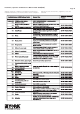
UNIT FLASH CODES
Various flash codes are utilized by the unit control board (UCB) to
aid in troubleshooting. Flash codes are distinguished by the short
on and off cycle used (approximately 200 ms on and 200 ms off).
To show normal operation, the control board flashes a 1 second
on, 1 second off heartbeat during normal operation. This is to
verify that the UCB is functioning correctly.
Do not confuse this with an error flash code. To prevent
confusion, a 1-flash, flash code is not used. Current alarms are
flashed on the UCB LED. Pressing and releasing the ALARMS
button on the UCB can check the alarm history. The UCB will
cycle through the last five (5) alarms, most recent to oldest,
separating each alarm flash code by approximately 2 seconds.
In some cases, it may be necessary to “zero” the ASCD for the
compressors in order to perform troubleshooting.
To reset all ASCDs for one cycle, press and release the UCB TEST
button once. See page 23 for table 10, Unit Flash Codes.
* Applicable only to DMS 150