
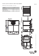
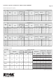
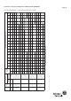
Product data

Page 20
Installation, Operation & Maintenance Manual # 036-1009(0608)
TROUBLE SHOOTING
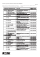
COOLING TROUBLE SHOOTING GUIDE
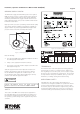
Troubleshooting of components may require opening the
electrical control box with the power connected to the unit. Use
extreme care when working with live circuits! Check the unit
nameplate for the correct line voltage and set the voltmeter
to the correct range before making any connections with line
terminals.
When not necessary, shut off all electric power to the unit prior
to any of the following maintenance procedures so as to prevent
personal injury.
NOTE : 2nd stage of cooling is available only in DMS 150.
* On calls for cooling, if the compressors are operating but the
supply air blower motor does not energize after a short delay
(the room thermostat fan switch is in the “AUTO” position).
1. Turn the thermostat fan switch to the ON position. If the
supply air blower motor does not energize, go to Step 3.
2. If the blower motor runs with the fan switch in the ON
position but will not run after the first compressor has
energized when the fan switch is in the AUTO position,
check the room thermostat for contact between R and G in
the AUTO position during calls for cooling.
3. If the supply air blower motor does not energize when the
fan switch is set to ON, check that line voltage is being
supplied to the blower contactor, and that the contactor is
pulled in. Check for loose wiring between the contactor and
the supply air blower motor.
4. If blower contactor is pulled in and voltage is supplied to
contactor, lightly touch the supply air blower motor housing.
If it is hot, the motor may be off on internal protection.
Cancel any thermostat calls and set the fan switch to AUTO.
Wait for the internal overload to reset. Test again when cool.
5. If blower contactor is not pulled in, check for 24 volts at the
contactor coil. If 24 volts are present but it is not pulled in,
replace the contactor.
6. Failing the above, if there is line voltage supplied at
contactor and it is pulled in, and the supply air blower motor
still does not operate, replace the motor.
7. If 24 volts is not present at blower contactor, check that 24
volts is present at the UCB supply air blower motor terminal,
“FAN”. If 24 volts is present at the FAN, check for loose
wiring between the UCB and blower contactor.
8. If 24 volts is not present at the “FAN” terminal, check for 24
volts from the room thermostat. If 24 volts are not present
from the room thermostat, check for the following :
a. Proper operation of the room thermostat (contact
between R and G with the fan switch in the ON position
and in the AUTO position during operation calls),
b. Proper wiring between the room thermostat and the
UCB, and
c. Loose wiring from the room thermostat to the UCB.
9. If 24 volts is present at the room thermostat but not at the
UCB, check for proper wiring between the thermostat and
the UCB, i.e. that the thermostat G terminal is connected to
the G terminal of the UCB, and for loose wiring.
10. If the thermostat and UCB are properly wired, replace the
UCB.
On calls for cooling, the supply air blower motor is operating but
compressor # 1 is not (the room thermostat fan switch is in the
“AUTO” position).
1. If compressor # 1 does not energize on a call for cooling,
check for line voltage at the compressor contactor 1, and
that the contactor is pulled in. Check for loose wiring
between the contactor and the compressor.
2. If compressor contactor 1 is pulled in and voltage is
supplied, lightly touch the compressor housing. If it is hot,
the compressor may be off on inherent protection. Cancel
any calls for cooling and wait for the internal overload to
reset. Test again when cool.
3. If compressor contactor 1 is not pulled in, check for 24 volts
at the coil. If 24 volts are present and contactor is not pulled
in, replace the contactor.
4. Failing the above, if voltage is supplied at compressor
contactor 1, it is pulled in, and the compressor still does not
operate, replace the compressor.
5. If 24 volts is not present at compressor contactor 1, check
for 24 volts at the UCB terminal, C1. If 24 volts is present,
check for loose wiring between C1 and the compressor
contactor.
6. If 24 volts is not present at the C1 terminal, check for 24
volts from the room thermostat at the UCB Y1 terminal. If 24
CAUTION
LABEL ALL WIRES PRIOR TO DISCONNECTION WHEN SERVICING
CONTROLS. WIRING ERRORS CAN CAUSE IMPROPER AND
DANGEROUS OPERATION, WHICH COULD CAUSE INJURY
TO PERSON AND/OR DAMAGE UNIT COMPONENTS. VERIFY
PROPER OPERATION AFTER SERVICING.
TROUBLESHOOTING OF COMPONENTS MAY REQUIRE OPENING
THE ELECTRICAL CONTROL BOX WITH THE POWER CONNECTED
TO THE UNIT. USE EXTREME CARE WHEN WORKING WITH LIVE
CIRCUITS! CHECK THE UNIT NAMEPLATE FOR THE CORRECT LINE
VOLTAGE AND SET THE VOLTMETER TO THE CORRECT RANGE
BEFORE MAKING ANY CONNECTIONS WITH LINE TERMINALS.
WARNING
* Applicable only to DMS 150