
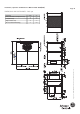
Product data

Page 17
Installation, Operation & Maintenance Manual # 036-1009(0608)
OPERATION SOUND POWER RATINGS
A sound power level is a measure of the total noise radiated by
the machine in all directions. It is a property of the machine and
is essentially independent of the measuring environment. Sound
power levels are useful to equipment manufacturers, buyers,
installers, and users for :
Calculating the sound pressure level from a machine at a •
given distance in a given environment.
Comparing the noise output from different machines. •
Setting specifications for the maximum permitted noise from •
a machine.
Comparing machines before and after modifications to •
reduce the noise.
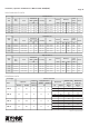
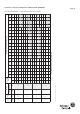
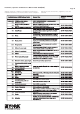
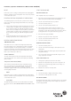
Sound power is measured in watts or picowatts, and sound
power levels are traditionally given in decibels (dB re 1pW). Refer
table 8 for sound power level of whole unit:
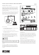
VOLT FREE CONTACT
All Saber units are supplied with volt free contact, Refer to
Electrical wiring schematic that are pasted inside the unit.
SEQUENCE OF OPERATIONS OVERVIEW
For these units, the thermostat makes a circuit between “R”
and “Y1” for the first stage of cooling. The call is passed to the
unit control board (UCB), which then determines whether the
requested operation is available and, if so, which components to
energize. For electric heat units, the UCB passes the call to the
electric heater. In both cases, when the “W1” call is sensed, the
indoor air blower is energized following a specified heating delay.
If at any time a call for both heating and cooling are present, the
heating operation will be performed. If operating, the cooling
system is halted as with a completion of a call for cooling
Heating always takes priority.
COOLING SEQUENCE OF OPERATION
CONTINUOUS BLOWER •
By setting the room thermostat fan switch to “ON” the supply air
blower will operate continuously.
INTERMITTENT BLOWER •
With the room thermostat fan switch set to “AUTO” and the
system switch set to either the “AUTO” or “HEAT” settings, the
blower is energized whenever a cooling or heating operation is
requested. The blower is energized after any specified delay
associated with the operation. When energized, the indoor
blower has a minimum run time of 30 seconds. Additionally, the
indoor blower has a delay of 10 seconds between operations.
NO OUTDOOR AIR OPTIONS •
When the thermostat calls for the first stage of cooling, the low
voltage control circuit from “R” to “Y1” and “G” is completed. For
first stage cooling, compressor #1, condenser fan motor will
energize. After completing the specified fan on delay for cooling,
the UCB will energize the blower motor.
When the thermostat calls for the second stage of cooling,
the low voltage control circuit from “R” to “Y2*” is completed.
Compressor # 2 is energized, provided it has not been locked
out. If there is an initial call for both stages of cooling, the UCB
will delay energizing compressor # 2 by 30 seconds in order to
avoid a power in rush. Once the thermostat has been satisfied, it
will de-energize Y1 and Y2*.
If the compressors have satisfied their minimum run times, the
compressors and condenser fan are de-energized. Otherwise,
the unit operates each cooling system until the minimum run
times for the compressors have been completed. Upon the final
compressor de-energizing, the blower is stopped following the
elapse of the fan off delay for cooling. To be available, a
compressor must not be locked out due to a high or low pressure
switch or freezestat trip and the anti short cycle delay (ASCD)
must have elapsed.
NOTE : 2nd stage of cooling is available only in DMS 150.
COOLING OPERATION ERRORS
Each cooling system is monitored for operation outside of the
intended parameters. Errors are handled as described below. All
system errors override minimum run times for compressors.
CAUTION
HOOK UP EMERGENCY SHUT - OFF BUTTON
Table 8: Sound Power Levels (DMS SABER UNITS)
* Applicable only to DMS 150