
Product data

Page 14
Installation, Operation & Maintenance Manual # 036-1009(0608)
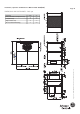
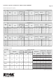
CHECKING SUPPLY AIR CFM
The RPM of the supply air blower will depend on the required
CFM, the unit accessories or options and the static resistances
of both the supply and the return air duct systems. With this
information, the RPM for the supply air blower and the motor
pulley adjustment (turns open) can be determined from the Fan
Performance Data Tables.
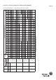
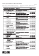
High speed drive accessories (containing a smaller blower pulley
and a shorter belt) are available for applications requiring the
supply air blower to produce higher CFM and/or higher static
pressures. Refer to the Drive and Pulley Data Table 6.
Note the following :
1. The supply air CFM must be within the limitations shown in
the Unit Application Data Table 1.
2. Pulleys can be adjusted in half turn increments.
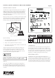
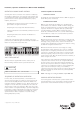
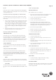
3. The tension on the belt should be adjusted as shown in the
Belt Adjustment Figure 9.
Start the supply air blower motor. Adjust the resistances in
both the supply and the return air duct systems to balance
the air distribution throughout the conditioned space. The
job specifications may require that this balancing be done by
someone other than the equipment installer.
SAFETY
This section of the IOM covers Safety Aspects applicable to
the York DMS Saber Roof Top Air Conditioners. Adherence to
the instructions detailed hereunder, will ensure the safety of
the operators, prevent damage to the equipment and prevent
accidents.
TERMINOLOGY
The internal section of the unit adjacent to moving parts and
electrical parts or devices is considered as the ‘danger zone’.
Prior to gaining access to these parts, it is necessary to acquire
the proper tools to deactivate the safety devices. The operators
are responsible for transport, installation, start up, service and
maintenance, including cleaning and trouble shooting.
OPERATIONAL SAFETY
York DMS Saber Roof Top Packages Air Conditioners in
conformance to the highest standards of operational as well as
operator safety. Nevertheless, hazards may occur if the units
are used for purposes other than the designed use(s), Units are
operated by untrained staff and / or Units are not operated in
conformance with general standards prevalent in the industry.
Figure 9: Belt Adjustment
FAILURE TO PROPERLY ADJUST THE TOTAL SYSTEM AIR
QUANTITY CAN RESULT IN EXTENSIVE BLOWER DAMAGE
WARNING
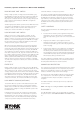
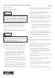
Figure 10: Unit Nameplate
Figure 11: Motor Nameplate
VkWPhHzrpm
A
Cos Ɏ
IP 54 ¨ 220 1.1 3 60 1110 5.4 0.72
ICL F Y 380 1.1 3 60 1110 3.1 0.72
IC 41 Y 460 1.1 3 60 1125 3.2 0.67
S 1 Y 380-415 1.1 3 50 935 3.3 0.69
Sr.#
Frame QSX90L6B02