Installation, Operation & Maintenance Manual - 50 Hz DMS Saber Series Air Cooled Packaged Air Conditioners 7.5, 8.5, 10.0 to 12.
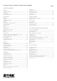
Installation, Operation & Maintenance Manual # 036-1009(0608) Page 2 TABLE OF CONTENTS GENERAL Safety considerations ................................................................ Inspection .................................................................................. Renewal parts ........................................................................... Product nomenclature ............................................................... 3 3 3 4 INSTALLATION Limitations .........................
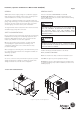
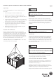
Installation, Operation & Maintenance Manual # 036-1009(0608) Page 3 GENERAL RENEWAL PARTS YORK Saber units are single package air conditioners equipped with optional factory installed electric heaters and designed for outdoor installation on a rooftop or steel structure. Refer to York USER’S MAINTENANCE and SERVICE INFORMATION MANUAL. It is strongly suggested that only genuine YORK Spare Parts are used to ensure efficient working of the unit and safety.
Installation, Operation & Maintenance Manual # 036-1009(0608) Page 4 NOMENCLATURE INSTALLATION LIMITATIONS Read these instructions before continuing this appliance installation. This is an outdoor combination heating and cooling unit. The installer must assure that these instructions are made available to the consumer and with instructions to retain them for future reference. These units must be installed in accordance with the applicable national and local safety codes.
Installation, Operation & Maintenance Manual # 036-1009(0608) Page 5 LOCATION WARNING Use the following guidelines to select a suitable location for these units : BEFORE LIFTING A UNIT, MAKE SURE THAT ALL PANELS ARE IN PLACE AND THAT ITS WEIGHT IS DISTRIBUTED EQUALLY ON ALL CABLES SO IT WILL LIFT EVENLY. 1. Unit are designed for outdoor installation only. 2. Condenser coils must have an unlimited supply of air. 3.
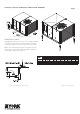
Installation, Operation & Maintenance Manual # 036-1009(0608) Page 6 FIGURE 3 : FIXED OUTDOOR AIR DAMPER Figure 3: Fixed Outdoor Air Damper CONDENSATE DRAIN Plumbing must conform to local codes. Use a sealing compound on male pipe threads. Install a condensate drain line from the one-inch FPT female connection on the unit to an open drain. NOTE : The condensate drain operates in a negative pressure in the cabinet. The condensate drain line MUST be trapped to provide proper drainage. See Figure 4.
Installation, Operation & Maintenance Manual # 036-1009(0608) Page 7 COMPRESSORS Units are shipped with factory adjusted compressor mountings and ready for operation. CAUTION DO NOT LOOSEN COMPRESSOR MOUNTING BOLTS. REMOVE COMPRESSOR SHIPPING BRACKETS BEFORE START-UP. FILTERS Two inch filters can be supplied with each unit. Filters must always be installed ahead of the evaporator coil and must be kept clean or replaced with same size and type.
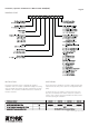
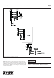
Installation, Operation & Maintenance Manual # 036-1009(0608) Page 8 Figure 6: Typical Field Wiring Schematic PHASING YORK Saber units are properly phased at the factory. Check for proper compressor rotation. If the blower or compressors rotate in the wrong direction at start up, the electrical connection to the unit is mis-phased. Change the incoming line connection phasing to obtain proper rotation. CAUTION UNITS ARE PROPERLY PHASED AT THE FACTORY.
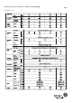
Installation, Operation & Maintenance Manual # 036-1009(0608) Page 9 PRODUCT DATA Table 4: Product Data
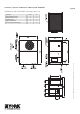
Installation, Operation & Maintenance Manual # 036-1009(0608) Page 10 Clearances inches mm Front (Compressor Access) 36 914 Back (Blower Fan Access) 36 914 Left (Filter Access) 30 762 Right (Condenser Coil) 36 914 Above (Condenser Air Discharge) 72 1829 Figure 7: DIMENSIONAL DATA AND CLEARANCES DMS 090, 100 & 120 DIMENSIONS AND CLEARANCES DMS 090, 100 & 120
Installation, Operation & Maintenance Manual # 036-1009(0608) Page 11 Clearances inches mm Front (Control Panel & Compressor Access) 36 914 Left (Filter Access) 30 762 Right (Condenser Coil) 36 914 Above (Condenser Air Discharge) 72 1829 Figure 8: DIMENSIONAL DATA AND CLEARANCES DMS 150 DIMENSIONS AND CLEARANCES : DMS 150
Installation, Operation & Maintenance Manual # 036-1009(0608) Page 12 DRIVE AND PULLEY DATA Low Static Drive Set Pitch Diameter Model DMS Motor Pulley Bush Min Max Pitch Dia Bush Fan Pulley mm Centre Distance RPM Range mm Min Max mm Belt Size 90 VAR 108 A1 1210 x 24 mm 78 102 SPA-180 1 1610 x 25 mm 180 628 822 490 1404 100 VAR 108 A1 1210 x 24 mm 78 102 SPA-170 1 1610 x 25 mm 170 665 870 490 1388 120 VAR 108 A1 1210 x 28 mm 78 102 SPA-170 1 1610 x 25 mm 170
2.2 1.5 2.2 12 / 12 12 / 12 15 / 15 100 120 150 4 3 Tab;e 7: Fan Performance Data 3 2.2 1.5 12 / 12 90 kW kW Size Optional DMS Standard Motor Fan Model 733 6000 2831 602 4500 2124 644 544 3750 1770 5000 2360 961 4800 2265 756 3500 1652 831 686 3000 1416 4000 1888 845 4000 1888 697 3000 1416 753 637 2500 1180 3400 1604 732 3250 1534 889 824 769 903 826 780 728 809 780 728 705 RPM 1.66 1.05 0.81 0.53 784 703 664 615 952 897 1.85 1.20 0.
Installation, Operation & Maintenance Manual # 036-1009(0608) Page 14 CHECKING SUPPLY AIR CFM The RPM of the supply air blower will depend on the required CFM, the unit accessories or options and the static resistances of both the supply and the return air duct systems. With this information, the RPM for the supply air blower and the motor pulley adjustment (turns open) can be determined from the Fan Performance Data Tables.
Installation, Operation & Maintenance Manual # 036-1009(0608) Page 15 OPERATION AND USE OF THE UNIT IN CONFORMANCE WITH GENERAL STANDARDS AND PROVISIONS 3. Warnings against coming into contact with electrical parts. YORK DMS Saber Roof Top Packaged Air Conditioners are designed for and are able to cool, heat, filter air and operate in the fan mode. Any other use is considered not in conformity with general provisions. The manufacturer is not responsible for any resulting damages.
Installation, Operation & Maintenance Manual # 036-1009(0608) Page 16 with this equipment. In addition to following the manufacturer’s installation instructions, care must be taken to ensure compliance with federal, state and local rules, regulations, codes and standards.
Installation, Operation & Maintenance Manual # 036-1009(0608) Page 17 OPERATION SOUND POWER RATINGS COOLING SEQUENCE OF OPERATION A sound power level is a measure of the total noise radiated by the machine in all directions. It is a property of the machine and is essentially independent of the measuring environment.
Installation, Operation & Maintenance Manual # 036-1009(0608) Page 18 HIGH PRESSURE LIMIT SWITCH extend the minutes of compressor operation. During cooling operation, if a high pressure limit switch opens, the UCB will de-energize the associated compressor, initiate the ASCD (anti short cycle delay), and, if the other compressor is idle, stop the condenser fan. If the call for cooling is still present at the conclusion of the ASCD, the UCB will re-energize the halted compressor.
Installation, Operation & Maintenance Manual # 036-1009(0608) Page 19 RESET START UP (COOLING) Remove the call for cooling, by raising thermostat setting higher than the conditioned space temperature. This resets any pressure or freezestat flash codes. PRESTART CHECK LIST ELECTRIC HEATING SEQUENCE OF OPERATIONS 1. Check the electrical supply voltage being supplied. Be sure that it is the same as listed on the unit nameplate.
Installation, Operation & Maintenance Manual # 036-1009(0608) Page 20 TROUBLE SHOOTING 5. If blower contactor is not pulled in, check for 24 volts at the contactor coil. If 24 volts are present but it is not pulled in, replace the contactor. 6. Failing the above, if there is line voltage supplied at contactor and it is pulled in, and the supply air blower motor still does not operate, replace the motor. 7.
Installation, Operation & Maintenance Manual # 036-1009(0608) Page 21 volts is not present from the room thermostat, check for the following : 7. 8. • 24 volts at the thermostat Y1 terminal. • Proper wiring between the room thermostat and the UCB, i.e. Y1 to Y1, Y2 to Y2. • Loose wiring from the room thermostat to the UCB. If 24 volts is present at the UCB Y1 terminal, the compressor may be out due to an open high pressure switch, low pressure switch, or freezestat.
Installation, Operation & Maintenance Manual # 036-1009(0608) Page 22 12. If none of the above correct the error, replace the UCB. * On a call for cooling, the supply air blower motor and compressor # 2 are operating but compressor # 1 is not (the room thermostat fan switch is in the “AUTO” position). NOTE : 2nd stage of cooling is available only in DMS 150. 1. Compressor # 2 is energized in place of compressor # 1 when compressor # 1 is unavailable for cooling calls.
Installation, Operation & Maintenance Manual # 036-1009(0608) Page 23 UNIT FLASH CODES EVERY SIX MONTHS In addition to the maintenance done every three months : • The condenser coils should be cleaned by spraying water over it at low pressure or with a brush while ensuring that the fins are not damaged. • Check all electrical connections and tighten them if required. • Clean all accessible electrical panels of dirt and dust.
Johnson Controls provides comfortable environments wherever you Live, Work or Travel Whether you’re at home, in a car, or in an office or workplace, chances are there’s a Johnson Controls product or service nearby, helping to make your environment more comfortable, safe and sustainable. Johnson Controls creates smart environments that improve the places where people spend most of their time – their homes, workplaces and vehicles.