
Operation Manual


(7) Check the electric quality, especially when the device is located by a big motor
(8) Be sure all ventilation chambers are not obstructed at all times.
(8) Do not put on heavy equipment and machinery on the system.
(9) Keep away from IAD at least 5cm in normal condition.
Instruction
Read the manual before you connect the system to its power source
1.2 Hardware Installation Procedure
The DV-2010 includes the following items.
- Two Analog Telephone Line and four 10/100Base-T Ethernet Cables
- User Guide
- A strut and an Wi-Fi antenna
- A splitter
- 12V power Adaptor
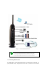
1.2.1 DV-2010 Installation steps
After the equipment is in place, see Figure 2 and follow the next procedure to install the
DV-2010.
Step 1. Connect one end of a telephone line cord into the wall jack and plug the other end to
the LINE input on the rear of the splitter.
Step 2. Connect one end of a telephone line cord into the PC of the splitter and plug the other
end to the ADSL input on the rear of DV-2010.
Step 3. Connect one end of a telephone line cord to the TEL input on the rear panel of the
IAD. Connect the other end to an analog telephone set
CAUTION
Connect the TEL port to a telephone only, never to a telephone wall jack