Triple Play Service IAD (DV-2010) USER Manual
COPYRIGHT This manual is proprietary to DAVOLINK Co., Ltd. and is protected by copyright. No information contained herein may be copied, translated, transcribed or duplicated for any commercial purposes or disclosed to third parties in any form without the prior written consent of DAVOLINK Co., Ltd. TRADEMARKS Product names mentioned in this document may be trademarks and/or registered trademarks of their respective companies.
SAFETY CONCERNS Introduction This document is User Manual of DV-2010S IAD. This manual describes how to operate and maintain the DV-2010 (Integration Access Device). Structure This document is composed of three chapters as follows : Chapter 1. Introduction System feature is outlined. Hardware specification and Software specification (i.e., interface type, service diagram, H/W function and S/W function) are in the DV-2010. Chapter 2. Installation It is a procedure for installation of DV-2010.
Conventions For product safety and correct operation, the following information must be given to the operator/user and shall be read before the installation and operation. This information may be set-off from the surrounding text, but is always preceded by a bold title in capital letters. WARNING Indicate a potentially hazardous situation which if not avoided, could result in death or serious injury.
SAFETY CONCERNS For product safety and correct operation, the following information must be given to the operator/user and shall be read before the installation and operation. Symbols Caution Indication of a general caution Restriction Indication for prohibiting an action for a product Instruction Indication for commanding a specifically required action ¨ SAMSUNG Electronics Co., Ltd.
This page intentionally left blank
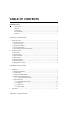
TABLE OF CONTENTS INTRODUCTION Introduction ............................................................................................................... 1 Structure .................................................................................................................... 1 Conventions ............................................................................................................... 2 Revision History ..................................................................................
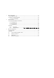
1 2 3 Basic configuration.......................................................................................................... 15 1.1 IP configuration on PC............................................................................................... 15 1.2 Connect to IAD through WEB ................................................................................... 20 1.2.1 Device information ..........................................................................................
CHAPTER 1. INTRODUCTION 1 System Overview DV-2010 is a kind of Home gateway for Triple Play service at home and SOHO environment. This device works like a central gateway for all the service enabling devices such as the VOIP, Internet and IP-TV functions. The IAD is a doorway where all services find their outlet to the service platforms, such as Internet Access concentrator, Call Switch and Media Farm. 1.
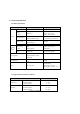
1.2 System Specification 1.2.1 Basic Specification Service Specification ADSL Interface ADSL/ADSL2/ADSL2 2 port Analog FXS, RJ-11 Interface Interface Feeding : -48V, 25mA Ringing : 45Vrms, 3 REN Ethernet Interface 10/100base-T(X), RJ-45 4 port with Auto-MDIX function (2 ports for STB, 2 ports for PC) 802.11b/g Wireless LAN Signaling and Protocol Remarks Auto Training PCMCIA Type-II 1 Antenna USB USB 1.
2 Software Features 2.1 IP Function Bridge Function PPPOE(LLC/SNAP) DHCP(Client, Server) IPCP Static IP Routing IP Filtering / MAC Filtering ICMP Proxy DNS UPnP SNMP (Agent & Tool) IGMP Proxy NAPT ALG (Application Layer Gateway) 2.2 Qos Function ToS Priority Queuing for Voice Dynamic Jitter Buffer Control VAD/CNG Echo cancellation ATM Traffic Management 2.3 Voice Functions MGCP(RFC3435) G.711a/u-law, G.729A, G.723.1 Echo cancellation : G.
RFC2364 PPP over AAL5 (PPPoA) RFC1577 (IPOA) 2.5 WLAN Interface IEEE 802.11b/g (Up to 54Mbps) Encrypted by WPA or WEB 64/128 bits 2dBi dipole antenna Wireless Bridge 2.6 Security Functions PAP/CHAP, PPDV-2010/L2DV-2010, IPSec ALG DIGEST authentication and encryption(MD5) Firewall (IP packet filtering, MAC filtering, DMZ) Service access control based on source and destination IP addresses 2.
CHAPTER 2. INSTALLATION 1 Installation Welcome to the DV-2010 which is based on Residential Gateway with integrated VoIP terminal and ADSL modem, router, firewall, and 54g AP (Access Point) all in one compact hardware and firmware platform. This section contains instructions that would allow you to configure user security setting and pleasant wireless setting quickly. DV-2010 works like PnP (Plug & Play) in order to get rid of complex setting for user convenience.
(7) Check the electric quality, especially when the device is located by a big motor (8) Be sure all ventilation chambers are not obstructed at all times. (8) Do not put on heavy equipment and machinery on the system. (9) Keep away from IAD at least 5cm in normal condition. Instruction Read the manual before you connect the system to its power source 1.2 Hardware Installation Procedure The DV-2010 includes the following items.
. NOTE The telephone must be switched to tone setting (not pulse) for the DV-2010 to operate properly. Step 4. Connect a straight-through Ethernet cable from your PC and STB to the 10/100 PC RJ-45 LAN port and STB ports on DV-2010. CAUTION LAN port 1 and 2 are only dedicated for STB. So do not connect PC to these ports. PC can only connect to LAN 3 and 4 port for the Internet. Step 5. Insert the power adaptor cable into the power connector on the DV-2010.
DV-2010 Cable connection Instruction LAD 1,2 port is dedicated for STB. Don¡t connect PC to these ports. PC can¡t get any IP address from IAD if PC is connected to STB port. 1.3.1 Connecting Ethernet cable The Straight cable is used for connecting LAN port to a terminal such as workstation, PC, laptop and STB.
because DV-2010 supports Auto MDI-X function on LAN port. Maximum length of RJ-45 should be less than 85m. RJ-45 cable (UDV-2010 cable) P C P o rt 1 2 3 4 5 6 7 8 1 2 3 6 : : : : Rx + Rx Tx + Tx - Ethernet Port pin connection RJ-45 Plug ( PC) Pin Signal 1 TX+ 2 TX3 RX+ 4 NC 5 NC 6 RX7 NC 8 NC connect RJ-45 Plug (PC Port) Pin Signal 1 TX+ 2 TX3 RX+ 4 NC 5 NC 6 RX7 NC 8 NC Connection between WAN port and modem 1.3.RJ-11 Plug (Analog phone/Fax) Pin Signal 1 NC 2 NC 3 Ring 4 Tip 5 NC 6 NC Connect Pin 1 2 3 4 5 6 RJ-11 Plug ( FXS port ) Signal NC NC Ring Tip NC NC
FXS port cable pin connection 1.3.3 ADSL port This port is used for connecting to CO(Central Office) Trunk, or connect to splitter. It use RJ-11 Connector. Pin 1 2 3 4 5 6 RJ-11 Plug ( PSTN ) Signal NC NC Ring Tip NC NC Connect Pin 1 2 3 4 5 6 RJ-11 Plug ( PSTN port ) Signal NC NC Ring Tip NC NC ADSL port pin connection 1.3.2 LED Status When DV-2010 comes up, you can judge the operation status of system by LED status. LED State Flashing Orange Description When power is present, When power is not present or fatal error POST failure or device malfunction Updating S/W image Blink per 0.
Power LED and PPP LED will be ON concurrently. Power LED and INET LED are orange blinking at the same time during S/W updating IAD booting time (all services up) : approximately one minute. IAD configuration file download time: approximately 2 seconds. IAD software image file download time: approximately 10 minute. IAD software image file burning time: approximately 2 minutes.
CHAPTER 3. CONFIGURATION 1 Basic configuration After installing system as like service network diagram 1, you should have to assigne IP address on the connected PC between 192.168.1.2 and 192.168.1.253 to access the DV-2010 using Web browser. But DHCP Server is enabled by default on IAD so user does not need to set IP address on PC manually. 1.1 IP configuration on PC DV-2010 supports DHCP server function to assign private IP to PCs. User can assign an IP address manually as like 192.168.1.XXX.
2. Double click ¡ Local area connection¡ in network connection window. 3. Click on ¡ Properties¡ button.
4. Select ¡ Internet protocol (TCP/IP)¡ and click on ¡ Properties¡ button. 5. Select ¡ IP address automatically and ¡ DNS address automatically¡ in internet protocol attribute window.
If you want to get a dynamic IP address from DV-2010, Click the ¡ obtain an IP address automatically. Otherwise you should select the ¡ Use the following IP address when you want to set an static IP on your computer. Instruction Do not assign the first 4 IP addresses for PC. The first four IP addresses are dedicated for STB. Instruction IP pool for local host should be more than 4 NOTE User can not disable DHCP function for VoD 6.
7. Open ¡ COMMAND PROMPT¡ window and Execute ¡ ipconfig¡ command to make sure that your PC is assigned IP address, subnet mask and default gateway value. NOTE Window98 and Window ME version support ¡winipcfg¡ Remember the IP Address value should be in 192.168.1.2~ 192.168.1.254, subnet mask should be 255.255.255.0, and Default Gateway should be 192.168.1.1 8. From windows system, go to ¡run¡. Type in ¡command¡. From ¡ Command Prompt¡ screen, typ e ¡ping 192.168.1.1¡ and press ¡Enter¡.
1.2 Access to WEB UI of IAD All Triple related configurations will be downloaded from TFTP server after DV-2010 is connected on DSL line and DSL connection is established completely. Configuration file includes PPP user name, password, voice setting and son on. User doesn¡t need to set complex settings to enjoy Triple Play service. Just plug and enjoy service. When you need set user specific setting like WLAN and Virtual server, access IAD using HTTP.
You can change the LAN IP address of IAD. IAD is enabled DHCP server by default to give IP addresses to its Host network devices from the next IP address you set on LAN interface. User can not disable DHCP server function for STB. The leased IP address from DHCP server will be refreshed after the leased time. Click on the Next button to setup Wireless LAN.
1.2.1 Device information After rebooting, below Device information will be come up. This page displays information about the current state of the DV-2010. If DV-2010 is connected to ADSL line properly, it shows current Line Rate (Upstream and Downstream) and the LAN IP address and DNS IP address for Internet. If the Downstream line rate is below than 14000 Kbps, you should contact DV-2010 service center.
2 Advanced Setup There are many advanced router features and Internet Telephony features supported by the DV-2010. These features are documented in this section, and include: 1. Various NAT Function(Virtual Servers, Port Triggering, DMZ Host) 2. Security(LAN IP address, port number filtering, Parental Control) 2.1 NAT (Network Address Translation) The DV-2010 is capable of operating in several modes that adjust how the device routes IP traffic.
There are many famous service names on the Service list. Select a service name, and enter the local IP address and click "Save/Apply" to forward IP packets for this service to the specified server. If there is no matched service name on the list, set service name at the custom server and put the service specific port number at the below column. After clicking on the save/apply button, the virtual server list will be come up. 2.1.
Click on the Add button to set up port triggering. A maximum 32 entries can be configured. Some applications such as games, video conferencing, remote access applications and others require that specific ports in the Router's firewall be opened for access by the applications. You can configure the port settings from this screen by selecting an existing application or creating your own (Custom application)and click "Save/Apply" to add it.
Above is an example setup that allows a special application to communicate with any PC on the Private LAN that tries to first connect with outgoing port numbers in the range of 1024 through 5180 and consequently triggers an opening of ports 1024 through 58,600 for bi-directional traffic for both TCP and UDP. This operation can only be effective for a single PC at a time, but can be used for any PC at a later time after the trigger ¡times out¡.
2.1.3 DMZ Hosting DMZ (De-militarized Zone) hosting (also commonly referred to as ¡Exposed Host¡) allows you to specify the ¡default¡ recipient of WAN traffic that NAT is unable to translate to a known local PC. This can also be described as a computer or small sub-network that sits between the trusted internal private LAN and un-trusted public Internet. The DMZ Host page is shown below. You may configure one PC to be the DMZ host.
In the example above, the PC with the IP address 192.168.1.8 has all of its IP Ports exposed to the WAN just as a PC on a bridging data mode would. However, the firewall is still activated here for specific DoS attacks, etc. 2.
types of data through the DV-2010 from the WAN to the LAN. 2.2.1 IP Filtering The DV-2010 can be configured to prevent local PCs from getting access the WAN by specifying those IP addresses that should be filtered. It is also possible to control outgoing IP traffic from LAN. This can be done from the IP Filtering page in the Advanced Security Menu. The IP Filtering page shows below. By default, all outgoing IP traffic from LAN is allowed, but some IP traffic can be BLOCKED by setting up filters.
3 Wireless Configuration The DV-2010 also serves as an 802.11b/g access point (AP). If DV-2010 has an 802.11 interface card installed, it can be configured using the web interface. If the wireless card is not installed, the Wireless menu on the left column of the web interface will not be present. 3.1 Wireless Basic Click on the Wireless menu to bring up the Wireless 802.11b/g Basic configuration page is shown below. This page allows you to configure basic features of the wireless LAN interface.
Setting Description Value List or Range Default Network Name (SSID) Sets the Network Name (also known as SSID) of this network. up to 32 character string containing ASCII characters any keyboard character DV201AM Network Type Selecting hides the network from active scans. Selecting Hide to reveals the network from active scans. Check or Leave Country Restricts the channel set based on country requirements.
Setting Description Value List or Range Default Network Authenticatio n Sets the network authentication method. 802.1X and WPA require that valid RADIUS parameters be set. WPA-PSK requires a valid WPA PreShared Key to be set. Disabled, shared, 802.1x, WPA, WPA-PSK, etc. Open Open Null authentication algorithm Grant any request for authentication 802.11 Shared Require static encryption key 64bit or 128bit strength 802.11 802.
Data Off WEP TKIP, AES, or TKIP + AES Disabled up to 32 character string containing ASCII characters with codes between 0x20 and 0x7e Disabled Network Key 1 thru Network Key 4 Disabled 5 or 13 ASCII characters or 10 or 26 hexadecimal digits Disabled Current Network Key Disabled 1 to 4 Disabled Enc Setting PassPhrase
Parameter Value List/Range depend on Network Authentication Settings Setting Description Value List or Range Default Network Authentication Sets the network autheShared Key Authentication Sets whether shared key authentication is required to associate. A valid network key must be set and selected if required. Depends on Network Authentication setting. See <. Optional PassPhrase Sets the text to use for WEP keys generation. Depends on Data Encryption setting.. Network Key 1 thru Network Key 4 Enter 5 ASCII characters or 10 hexadecimal digits for a 64-bit key. Enter 13 ASCII characters or 26 hexadecimal digits for a 128-bit key.
3.4 Wireless Advanced This page allows you to configure advanced features of the wireless LAN interface. You can select a particular channel on which to operate, force the transmission rate to a particular speed, set the fragmentation threshold, set the RTS threshold, set the wakeup interval for clients in power-save mode, set the beacon interval for the access point, set XPress mode and set whether short or long preambles are used. Click "Apply" to configure the advanced wireless options.
The Beacon and DTIM Intervals should be left at 100 ms and 1 ms respectfully for successful operation with most client cards and WiFi¢ operation compliance. The Beacon Interval specifies how often packets are sent by the Access Point (AP) to synchronize a wireless network and its clients. The DTIM (Delivery Traffic Indication Message) Interval is a countdown informing the wireless clients of the next window for listening to broadcast and multicast messages.
54g¢ Network Mode Sets the network mode. Max Compatibility interoperates with the widest variety of 54g and 802.11b clients. 54g Only accepts only 54g clients. Max performance provides the highest throughout and accepts only 54g clients; nearby 802.11b networks may have degraded performance. Max Compatibility, 54g Only, Max Performance Max Compatibility 54g¢ Protection In Auto mode the AP will use RTS/CTS to improve 802.11g performance in mixed 802.11g/802.11b networks.
► Should be away from Micro wave at least 5M. If there is no way to avoid from microwave, set channel 1,2,12,13 ► When IAD is located at the same place with Plasma lamp, set Should be away from Bluetooth at least 5M channel 11~13 ► If there is a walkie-talkie near IAD, should set the channel which is not covered the same Frequency.
This page intentionally left blank
DV-2010 User Manual ¨200 2 DAVOLINK Co., Ltd. All rights reserved. Information in this document is proprietary to DAVOLINK No information contained here may be copied, translated, transcribed or duplicated by any form without the prior written consent of DAVOLINK. Information in this document is subject to change without notice. Visit us at htDV-2010://www.davolink.