UNIVERSAL ANEMOMETER INTERFACE I N S TA L LA TI O N M A N U A L With this interface, some anemometers not manufactured by Davis Instruments can be used with the Vantage Pro2. Non‐Davis anemometers must have AC voltage output signals. The frequency of the AC signal must be linearly propor‐ tional to the wind speed. This interface has been tested with R. M. Young anemometers, model number 05103; and with NRG anemometers, model 1900 NRG#40C or MAX40. How‐ ever, the interface is not limited to those products.
Tools for Setup In addition, you will need some or all of the following materials: • • • • Adjustable wrench or 7/16ʺ wrench Compass or local area map (to adjust wind direction, if needed) Drill and 3/16ʺ (5 mm) drill bit (if mounting on a vertical surface) Carpenter’s level (if mounting on a vertical surface) If you are installing a Davis Integrated Sensor Suite (ISS) or Anemometer Transmitter Kit and the non-Davis anemometer at the same time: Install your ISS first, following the instructions in the ins
If you are replacing an already mounted and installed anemometer: Remove the old anemometer from its current location The following two steps assume that your ISS, with standard anemometer, is already mounted. Disconnect the old anemometer from the ISS transmitter Open the Vantage Pro2 SIM Box and unplug the anemometer cable from the receptacle labeled WIND on the SIM. Remove the foam insert and then guide the cable out of the box.
Mount the New Anemometer Refer to the manufacturer’s directions to mount the new anemometer. However, keep the following factors in mind as you choose a location for your anemometer and the interface shelter: • Mount the anemometer at least 4ʹ (1.2 m) above the roofline for accurate wind readings. • Mount the interface shelter nearby, with the solar panel facing the sun. In the Northern Hemisphere, position the transmitter shelter with solar panel facing south for maximum sun exposure.
Mounting on a vertical surface 1. With a 3/16ʺ (5 mm) drill bit, drill two holes approximately 2ʺ (50 mm) apart. Use a carpenter’s level to ensure the holes are level. 2. Drill two more holes 7‐1/32ʺ (17.9 cm) below the upper Lag Screw Flat holes. Washer 3. Insert the 1/4ʺ x 1‐1/2ʺ lag screws through the flat washers, and through the holes at the top of the shelter into the post. Using an adjustable wrench or 7/16ʺ wrench, tighten the lag screws. 4.
Insert the Battery 1. Insert the 3‐volt lithium battery into the battery holder, matching the “+” sign on the battery with the “+” sign inside the interface shelter. Note: It will take approximately one minute for the capacitor to charge and the unit to begin functioning. Connect the Cable to the New Anemometer R. M. Young 05103: 1. Open the junction box on the anemometer and cut the jumper wire. (Its location is marked “JUMP FOR COMMON REF”.) 2. Unscrew the sealing nut on the strain relief. 3.
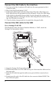
Connect the Anemometer Cable to the Interface 3-Volt Lithium Battery Solar Panel Cable Anemometer Selector Jumper (labeled “P2”) “OUT” RJ Jack P2 3 2 1 IN OUT Cable Clamp Cable Clamp Mount “IN” RJ Jack Square Black Grommets Anemometer Cable ISS Cable 1. Open the interface shelter. Feed the loose end of the 6‐conductor anemometer cable up through the square black grommet at the base of the shelter. (The Davis shelter has two of these grommets to provide weather‐resistant entrances for cables.
Connect the ISS Cable to the Interface 1. Feed one end of the 4‐conductor ISS cable into the same grommet as the 6‐ conductor cable. 2. Plug it into the RJ jack labeled “OUT.” 3. Secure both cables inside with the cable clamp. Place the cable clamp over both cables between the grommet and the receptacle. Secure the cable clamp to the shelter by threading the provided #6 screw through the washer and cable clamp and then screwing it into the cable clamp mount inside the hous‐ ing. (See illustration on page 7.
5. Make sure that the cables lie flat on the bottom of the cable access port. 6. Firmly insert the foam in between the cables and the top of the cable access port, taking care to ensure that the foam seals the access port entirely, leaving no holes or gaps large enough for weather or insects. Note: Refer to your Vantage Pro2 ISS Installation Manual for more information. For an Anemometer Transmitter Kit 1.
Configure the Console Note: If your are not using an R.M. Young anemometer, you must use a Vantage Vue console. This console allows for the special calibration needed. Vantage Pro2 Console If your anemometer required that P2 pins 1 & 2 be shunted (e.g. R.M. Young, see page 7) follow these instructions to configure your Vantage Pro2 console: 1. Enter Setup Mode by pressing DONE and the “‐” key at the same time. 2.
If You Do Not See Current Wind Readings Refer to your ISS Installation Manual or Anemometer Transmitter Kit Manual. Note: It is assumed that the ISS or Anemometer Transmitter Kit has been installed and tested as instructed in the ISS or Anemometer Transmitter Kit manual. A Note on Securing Cables Prevent fraying or cutting of cables by securing them so they will not whip about in the wind. Secure a cable to a metal pole by wrapping electrical tape around them both.
FCC Part 15 Class B Registration Warning This equipment has been tested and found to comply with the limits for a class B digital device, pursuant to Part 15 of the FCC Rules. These limits are designed to pro‐ vide reasonable protection against harmful interference in a residential installation. This equipment generates, uses and can radiate radio frequency energy and, if not installed and used in accordance with the instructions, may cause harmful interfer‐ ence to radio communications.