Sensor Suite Installation Manual C 3465 Diablo Ave., Hayward, CA USA 510.732.9229 • www.davisinstuments.
Table of Contents Introduction ........................................................................................................1 Included Components and Hardware .................................................................1 Vantage Vue Sensor Suite Components .................................................1 Hardware ................................................................................................2 Tools Needed ....................................................................
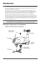
Introduction The Vantage Vue® wireless sensor suite collects outside weather data and sends the data wirelessly to a Vantage Vue console via a low-power radio. The sensor suite is solarpowered and includes a battery back-up. The Vantage Vue sensor suite contains a rain collector, temperature/humidity sensor, anemometer, and wind vane. The temperature/humidity sensor is mounted in a passive radiation shield to minimize the impact of solar radiation on sensor readings.
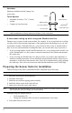
Hardware Hardware included with the Vantage Vue sensor suite: U-Bolt Tools Needed • • Adjustable wrench or 7/16” (11 mm) wrench Compass or local area map Debris screen Backing plate 1/4” lock washers 1/4” hex nuts Note: 0.05” Allen wren If any of the hardware components are missing or not included, contact Customer Service toll free at 1-800-678-3669 about receiving replacement hardware or other components.
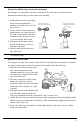
Attach the Wind Cups to the Anemometer The Vantage Vue anemometer measures wind speed. The wind cups are mounted on the anemometer shaft on the top of the sensor suite assembly. 1. Gently slide the wind cup assembly down onto the anemometer’s stainless steel shaft as far as it will go, as shown. 2. Use the Allen wrench provided to tighten the set screw near the top of the “hub” section of the wind cups, as shown. Ensure that the set screw is screwed in fully and is tight. 3.
Install the Rain Collector Tipping Spoon Assembly Tipping spoon assembly slot 1. Locate the tipping spoon assembly slot on the underside of the sensor suite base. 2. Insert the wider end of the tipping spoon assembly into the slot first, sliding it under the raised lip of the slot. 3. Fit the narrow end into the slot and tighten the thumbscrew securely.
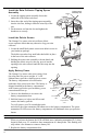
Note: If you have not already set up and powered your Vantage Vue console, do so before continuing with the sensor suite installation. For best reception, the console and sensor suite should be at least 10 feet (3 meters) apart. 4. The console or WeatherLink Live acquires the radio signal and populates data fields. This usually occurs quickly, but in some environmental conditions it can take up to 10 minutes.
1. Push and hold the transmitter ID button until the LED begins flashing quickly. This indicates it is in the setup mode. 2. Release the button, and the LED will go dark. 3. Push the button the number of times equal to your desired new transmitter ID. That is, if you want to change the ID to 3, push the button three times; for a desired ID of 4, push the button four times. After four seconds have elapsed with no further presses, the LED will blink the same number of times as the new transmitter ID.
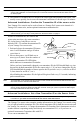
Installing the Sensor Suite Choosing a Location for the Sensor Suite The sensor suite assembly includes the rain collector, wind vane, anemometer, temperature and humidity sensors, radiation shield, and SIM housing. You will use the U-bolt and associated nuts and washers that are included with your sensor suite mounting hardware package to install the sensor suite on a pole. (See “Hardware” on page 2.
Sensor Suite Installation Guidelines • • • • • • Ideally, mount the sensor suite so that it is between 5’ (1.5 m) and 7’ (2.1 m) above the ground in the middle of a gently sloping or flat, regularly mowed grassy or naturally landscaped area that drains well when it rains. You can also mount the sensor suite on the roof, between 5’ (1.5 m) and 7’ (2.1 m) above the roof surface. For areas with average maximum yearly snow depths over 3’ (0.9 m), mount the sensor suite at least 2’ (0.6 m) above this depth.
Sensor Suite Installation Guidelines Recommended Accessories for Pole Mounting • Use the Mounting Tripod (#7716) for easiest mounting. • Use the Mounting Pole Kit (#7717) to raise the installation height of the sensor suite by up to 37.5" (0.95 m). General Guidelines for Installing on a Pole • With the supplied U-bolt, the sensor suite can be mounted on a pole or rod having an outside diameter ranging from 1" to 1.75" (25 – 44 mm).
Sensor Suite Installation Guidelines 7. If you are in the Northern Hemisphere, rotate the sensor suite on the pole so that the solar panel is facing south; if you are in the Southern Hemisphere, rotate the sensor suite so that the solar panel is facing north. The more precisely the solar panels face due south or north, the more accurate your wind direction readings will be. Note: Do not rely on a compass unless it is properly calibrated.
Maintenance and Troubleshooting Maintenance Note: If you are using WeatherLink Live, it is a good idea to power it down before maintaining your sensor suite so that it does not collect erroneous data during the maintenance steps. Cleaning the Radiation Shield The outer surface of the radiation shield should be cleaned when there is excessive dirt and build-up on the plates. Use a damp cloth to clean the outer edge of each ring.
Troubleshooting To clean the tipping spoon assembly, it must first be removed from the sensor suite base. 1. Unscrew the thumbscrew securing the tipping spoon assembly to the sensor suite base. Slide the assembly down and away from the base. 2. Use a damp, soft cloth to gently remove any debris from the tipping spoon assembly, being careful not to damage any moving parts or scratch the spoon. 3. When all parts are clean, rinse with clear water, and replace the assembly.
Troubleshooting Problems Using Two Transmitting Stations A single Vantage Vue console can receive signals from one sensor suite, either a Vantage Vue or a Vantage Pro2 sensor suite, and an optional anemometer transmitter kit. Make sure the transmitter IDs are configured correctly. See your Vantage Vue Console Manual for information on configuring transmitter IDs. Most Common Rain Collector Problem “My rain data seems too low.
Appendix A: Specifications See complete specifications for your Vantage Vue station on our website: www.davisinstruments.com Integrated Sensor Suite (ISS) Specifications Operating Temperature................................... -40° to +150°F (-40° to +65°C) Non-operating (Storage) Temperature ............-40° to +158°F (-40° to +70°C) Current Draw (ISS SIM only)........................... 0.20 mA (average), 30 mA (peak) at 3.3 VDC Solar Power Panel (ISS SIM) .......................... 0.