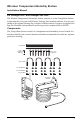
Wireless Temperature/Humidity Station Installation Manual For Vantage Pro2™ and Vantage Pro2 Plus™ The Wireless Temperature/Humidity Station, referred to as the Temp/Hum Station in this manual, is for use with Wireless Vantage Pro2 weather stations. It is not compatible with original Vantage Pro wireless weather stations. Owners of original Vantage Pro Weather stations should use Davis product number 6380 or 6380OV.
Tools for Setup In addition to the hardware provided, you will need some or all of the following materials: • Small phillips head screwdriver • Adjustable wrench or 7/16" wrench • Ballpoint pen or paper clip (small pointed object of some kind) • Drill and 3/16" (5 mm) drill bit (if mounting on a flat, vertical surface) Installation Steps For ease of installation, please follow the steps in the order presented.
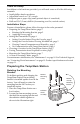
. When the screws are completely loosened, lift the mounting bracket away from the radiation shield. 4. Rotate the mounting bracket and replace it on the radiation shield. 5. Fasten the mounting bracket in place using the three long screws as shown in the illustration right. 4" Bolts Re-install Mounting Bracket Lock Washers Flat Washers Radiation Shield Assembly Applying Power 1.
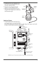
2. Plug the Temp/Hum Sensor Cable into the jack labeled TEMP/HUM on the bottom right hand corner of the SIM board. Take care to carefully dress the cable through the black rubber grommet on the bottom right hand side of the shelter. Also, dress the cable through the cable clamp by first removing the screw connecting it to the shelter, dressing the cable through the round part of the clamp, and then driving the screw back through the holes in the clamp and into the cable clamp mount. 3.
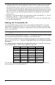
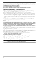
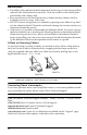
Battery Holder ON 1 2 3 4 DIP Switches DIP Switches in Top-right Corner of SIM (Illustration has been enlarged for clarity) Setting Console Station ID on the Console 1. Put your console into Setup Mode — press and hold DONE and press the DOWN arrow (-). The console will show you Screen 1: Transmitters. You should see the words: “RECEIVING FROM...” and “STATION NO.” followed by the transmitter IDs that your console detects.
This confirms communication between your Temp/Hum Station and the console. If you are not receiving the sensor readings on the console go the the next section, “No Communication with Temp/Hum Station”. 3. Close the SIM Shelter cover. See page 4. 4. Go on to “Choosing a Location for the Temp/Hum Station” on page 7. No Communication with Temp/Hum Station 1. First, verify that the console is powered and is not in Setup Mode. Exit Setup Mode by pressing DONE and holding it for a moment. 2.
Choosing a Location for the Temp/Hum Station Consider the following factors as you choose a location: • Do not mount the station near any source of cold or heat that might distort temperature measurements. • The station’s radiation shield works best in a location with a steady breeze. Mount it away from fences, buildings, trees, or other obstructions. • Mount the station over vegetation or soil if possible. • Do not install over or near sprinklers.
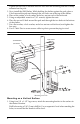
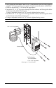
3. 4. 5. 6. 7. 8. Tighten all four sets of washers and hex nuts until the mounting bracket is firmly mounted on the pole. Next, install the SIM Shelter. While holding the shelter against the pole, place a U-bolt around the pole and through the two holes on at the top of the shelter. Place a flat washer, a lock washer and a hex nut on each of the bolt ends. Using an adjustable wrench or 7/16" wrench, tighten the nuts.
2. Next, install the SIM Shelter. With a 3/16" (5 mm) drill bit, drill two holes approximately 2" (50 mm) apart. Use a carpenter’s level to ensure the holes will be level. 3. Drill two more holes 7-1/32" below the upper holes. 4. Insert the 1/4" x 1-1/2" lag screws through the flat washers, and through the holes at the top of the shelter into the post. Using an adjustable wrench or 7/16" wrench, tighten the lag screws. 5.
Maintenance • The ability of the radiation shield to keep fresh air flowing over the sensors will be reduced if the shield plates become dirty. Clean the surfaces of the shield plates periodically with a damp cloth. • Keep areas between the shield plates free of debris that may obstruct air flow. Examples are leaves, twigs, webs, nests. • DO NOT remove nesting insects or animals by spraying insect killer of any kind into the radiation shield.
Specifications General Operating Temperature . . . . . . . . . . . . . . . . . . . . . . -40° to +150° F (-40° to +65° C) Non-operating Temperature . . . . . . . . . . . . . . . . . . . -50° to +158° F (-45° to +70° C) Current Draw, Sensors & Transmitter only . . . . . . . . 0.14 mA (average), 30 mA (peak) at 3 VDC Battery: Sensors & Transmitter. . . . . . . . . . . . . . . . . CR-123 3-Volt Lithium cell Battery Life . . . . . . . . . . . . . . . . . . . . . . . . . . . . . . .
Product Numbers: 6382, 6382OV Davis Instruments Part Number: 07395.242 Wireless Temperature/Humidity Station Installation Manual Rev. B Manual, 12/28/09 This product complies with the essential protection requirements of the EC EMC Directve 2004/108/EC. 3465 Diablo Avenue, Hayward, CA 94545-2778 U.S.A. 510-732-9229 • Fax: 510-732-9188 E-mail: info@davisnet.com • www.davisnet.