USER MANUAL Ethernet Gateway and Node Product number 6810 and 6805 R Davis Instruments, 3465 Diablo Avenue, Hayward, CA 94545-2778 U.S.A. • 510-732-9229 • www.davisinstruments.
FCC Part 15 Class B Registration Warning This equipment has been tested and found to comply with the limits for a Class B digital device, pursuant to Part 15 of the FCC Rules. These limits are designed to provide reasonable protection against harmful interference in a residential installation. This equipment generates, uses, and can radiate radio frequency energy and, if not installed and used in accordance with the instructions, may cause harmful interference to radio communications.
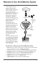
Welcome to Your EnviroMonitor System An EnviroMonitor System includes a Gateway and a number of Nodes, each with up to four sensors that form an advanced mesh network operating at 902 - 928 MHz (868 MHz in the EU). The Nodes transmit the sensor data to a “mesh parent,” either the Gateway or another Node. The Gateway then sends the data via ethernet connection to WeatherLink.com. EnviroMonitor can be customized for different sized installations. Each Gateway can receive 20 or more Nodes.
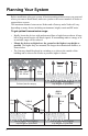
Planning Your System Before installation, plan your system. After determining which sensors you want and where you want to install them, make sure you have the correct number of Nodes to support those sensors. The maximum distance between two Nodes and a Gateway and a Node will vary depending on many factors including environment, height, terrain and RF noise. To get optimal transmission range: • Ideally, locate the devices with unobstructed lines of sight between them.
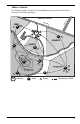
Make a Sketch It is helpful to make a sketch of your installation to get an idea of where the Gateway and Nodes should go. Dav is R Peppers S S N N Hw y. 1 0 SAMPLE FARM d.
Siting the Nodes • Ideally, the mesh network will be most effective at “self healing” any temporarily impaired transmission paths if each Node has more than one way to reach the Gateway. While the system is designed to handle a mesh, a “star” or nodes in single lines, it is a good idea whenever possible to site each node so that it is within transmission distance of either two (or more) other Nodes, or the Gateway and another Node.
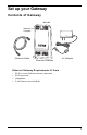
Set up your Gateway Contents of Gateway Blue LED Capacitive Touchpad AC Adapter Ethernet Cable Ethernet Gateway Ethernet Gateway Requirements & Tools • Wi-Fi or router Ethernet internet connection • Wi-Fi password • Smartphone • 4 AA batteries (not included) 5
Power-up and Connect your Gateway Install the EnviroMonitor App 1. Install the EnviroMonitor app on your Smartphone. Find the app by searching for the Davis EnviroMonitor app in the iOS App Store or Google Play Store. The EnviroMonitor app will guide you through creating an account on WeatherLink.com, adding the Gateway, adding Nodes to the Gateway, and adding sensors to the Node. EnviroMonitor App Add Gateway Open the App to create your account on WeatherLink.
Install the WeatherLink App and Create Your Account 2. Install the WeatherLink mobile app on your smartphone. Find the app by searching for the Davis WeatherLink app in the iOS App Store or Google Play Store. 3. In the app, create your account on WeatherLink.com. Note: You will use the user name and password you have set up to access your page on WeatherLink.com from your computer as well. You will only have to enter your name and password the first time you open the app unless you log out.
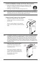
3. Plug the included Ethernet cable into the socket on the Gateway. Connect the other end of the cable to your router. You will see green and amber lights when the connection has been established. 4. The blue LED light will begin flashing indicating that the device is ready to connect to the smartphone app. Tip: Ethernet Cable Socket The device will “go to sleep” and the blue LED will turn off if you don’t connect the device within a few minutes.
Set Up Nodes and Sensors Contents of Node Rechargable Lithium Battery Compartment (battery in hardware kit) Bluetooth status LED Mesh status LED Solar Panel Cable Solar Panel Jack Lithium Battery Battery Compartment Door Door Tabs D-Cell Battery Compartment (batteries not included) Sensor Ports Mesh Antenna Hardware Kit U-Bolts 1/4" Lock Washers 1/4" Hex Nuts Backing Plates 1/4" x 1 1/4" Lag Screws Green 6-Wire Sensor Connectors Cable Ties Adhesive Mounts #6 x 3/8 Screws (disregard) Precision
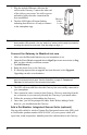
Requirements & Tools for Installation of Nodes and Sensors • • • • • Note: Included precision/miniature slotted screwdriver; ideal size: 2.5 mm or 3/32”; see actual size image of screw head and screwdriver blade at right. Four D-cell batteries Smartphone with EnviroMonitor app installed. See page 6: Install the EnviroMonitor App.
3. Plug in the solar panel cable. Connect Node to Gateway 1. Take the Node and smartphone to the general location in which you wish to install your Node. Make sure the phone’s Bluetooth is on. 2. Open the app on the smartphone. 3. Open the door of the Node. (This turns the Node’s Bluetooth on.) The Bluetooth status LED will blink blue. See the illustration on page 9: Contents of Node. 4. In the app, select the Gateway to which this Node will send its data. 5. Tap Add Node. 6.
1. Install the sensor in the environment per the manufacturer’s instructions, making sure the Wire each sensor as sensor is installed within cable reach of the Node directed in when it is mounted. the App 2. On your smartphone, open the EnviroMonitor app and select this Node. Tap Add Sensor. From 6 5 the menu, first select the sensor type, then the 4 3 2 specific sensor. Follow the wiring diagram in the 1 app to correctly wire the sensor into one of the green 6-wire sensor connectors. Using a 2.
Mount the Node The Node can be mounted on a pole or a flat surface such as a wall or a wooden post. It is important that the Node be mounted so that the solar panel gets the greatest amount of sunshine -- the solar panel should be facing south (in the Northern Hemisphere) or north (in the Southern Hemisphere). Tip: Mounting the Node may be easier if done by two people. Mounting On a Fence Post or Pole Mount the Node onto a fence post or a pole with an outside diameter of 0.84'' to 1.
Mounting on a Flat Surface Attach the Node to the mounting surface in the desired location using the lag screws and backing plates as shown below. Use a pencil or a center-punch to mark the location of the pilot hole. ® Manage Your Data Log on to WeatherLink.com to view and manage your data. You can also use view and manage your data on your smartphone with the Mobilize app. Find the app by searching for Davis Mobilize in the iOS App Store or Google Play Store.
Maintenance The solar panel on your Node will perform well even with dust on it. However, keep the panel charging optimally by periodically cleaning any bird droppings, heavy dust, dirt, snow, leaves, or insect nests or webs from the solar panel. Cleaning frequencywill depend on your installation, but at least once a year. Those near roads or railroad tracks, for example, may collect more dust and dirt than those in the center of a field. Use a soft, damp cloth to remove any debris from the solar panel.
How can I tell if my Node batteries are getting too low? The mesh LED will be solid or blinking amber to show that the Node’s batteries are low. See the table above. You can also see the battery power in the app: choose this Node’s Gateway, then this Node, then Node Power. What do the Node status LEDs indicate? Node Status LEDs LED Behavior Indicates What to do No BLE LED. BLE radio is in low-power mode. Close, then open the door to activate the BLE radio. BLE LED flashes blue.
Contacting Davis Technical Support For questions about installing or operating your Gateway or Nodes, please contact Davis Technical Support. We’ll be glad to help. Online www.davisinstruments.com See the Weather Support section for copies of user manuals, product specifications, application notes, software updates, and more. E-mail support@davisinstruments.com Telephone (510) 732-7814 Monday - Friday, 7:00 a.m. - 5:30 p.m. Pacific Time.
Specifications Gateway Operating Temperature. . . . . . . . . . . . . . 32° to +140°F; 0° to +60°C Current Draw . . . . . . . . . . . . . . . . . . . . .Average: 100 mA; Peak 700mA Housing Material. . . . . . . . . . . . . . . . . . . Rugged ASA Plastic Backup Batteries . . . . . . . . . . . . . . . . . . 4 AA (not included) Battery Life . . . . . . . . . . . . . . . . . . . . . . . 5 days AC Adapter . . . . . . . . . . . . . . . . . . . . . . . 5 VDC, 1000 mA Wi-Fi Frequency Range & Power . . . . . .