Wireless Temperature Station Installation Manual Note: The Wireless Temperature Station (Davis product number 6372) can be used with wireless Vantage Pro2™ weather stations, and/or wireless Weather Envoy (6316) and Envoy8X (6318).
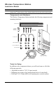
Installation Steps For ease of installation, please follow steps in the order presented. • Prepare the temperature station, page 3 • Insert the battery, page 3 • Set the transmitter ID, page 3 • Set ID on the temperature station using DIP switches, page 4 • Set the console to recognize the signals, page 4 • View current temperature, page 5 • (If you don’t see temperature from the correct Station No.
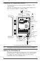
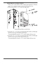
Preparing the Temperature Station The illustration below shows the Sensor Interface Module, or “SIM”, inside the shelter. Insert the 3-volt lithium battery into the battery holder, matching the “+” sign on the battery with the “+” sign on the SIM.
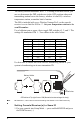
Note: The transmitter and receiver communicate with each other only when both are set to the same ID. The factory default transmitter ID is ‘1’. Looking at the table below, you can see that means the DIP switches are in the OFF position when each transmitting station leaves the factory, whether it is an ISS, a wireless temperature station, or another kind of station. The ISS is included with every Wireless Vantage Pro2, so the console/ receiver is set to find the ISS on ‘1’.
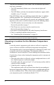
2. 3. 4. 5. Screen 1: Transmitters displays on the console screen. You should see the words: “RECEIVING FROM...” and “STATION NO.” followed by the transmitter IDs that your console detects. One of these should be the ID number you just set on the temperature station transmitter. If you don’t see it, make sure the console is within 10' of the transmitter, and verify that you set the DIP switches correctly. If you still don’t see it, go to “TEST mode” in the next section.
This puts the transmitter in TEST mode. An LED indicator light flashes each time it transmits: • The LED immediately flashes once to show that the light itself functions. • The LED flashes each time the transmitter broadcasts a signal, which should be every 2.5 seconds. If the LED flashes only once and then remains dark, there is a problem with the transmitter. See “contacting Davis Instruments” on page 10.
The following factors should be considered whether your temperature probe is inside a radiation shield or not: • If placing the probe on the outside of a building, a good location is under the eaves on the north side of the building. (In the Southern Hemisphere, the south side of a building is preferable.) • Place the probe at least 10' (3 m) away from lights or lamps. • Place the probe at least 5' (1.5 m) from chimneys and exhaust vents.
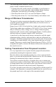
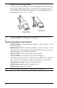
Mounting the Wireless Temperature Station Mounting on a Pole 1. While holding the shelter against the pole, place a U-bolt around the pole and through the two holes on at the top of the shelter. 2. Place a flat washer, a lock washer and a hex nut on each of the bolt ends. Lock Flat Washer Washer Hex Nut U-Bolt Mounting Temperature Station on a Pole 3. Using an adjustable wrench or 7/16" wrench, tighten the nuts. 4.
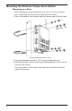
Mounting on a Vertical Surface 1. With a 3/16" (5 mm) drill bit, drill two holes approximately 2" (50 mm) apart. Use a carpenter’s level to ensure the holes will be level. 2. Drill two more holes 7-1/32" below the upper holes. Flat Washer Lag Screw Mounting Temperature Station on a Vertical Surface 3. Insert the 1/4" x 1-1/2" lag screws through the flat washers, and through the holes at the top of the shelter into the post. Using an adjustable wrench or 7/16" wrench, tighten the lag screws. 4.
A Note on Securing Cables To prevent fraying or cutting of cables, secure them so they will not whip about in the wind. Secure a cable to a metal pole by wrapping electrical tape around them both. Make sure cables are secure by placing clips or ties approximately every 3 – 5' (1 – 1.6 m). Cable Tie Cable Clip Note: Do not use metal staples or a staple gun to secure cables. Metal staples—especially when installed with a staple gun—have a tendency to cut the cables.
Specifications General Operating Temperature . . . . Non-operating Temperature Sensor Type . . . . . . . . . . . . Current Draw . . . . . . . . . . . . . . . . . . . . . . . . . . . . . . . . . . . . . . . . . . . . . . . Battery . . . . . . . . Battery Life . . . . . Housing Material . Dimensions . . . . . . . . . . . . . . . . . . . . . . . . . . . . . . . . . . . . . . . . . . . . . . . . . . . . . . . . . . . . . . . . . . . . . . . . . Weight. . . . . . . . . . . . . . . . .
FCC Part 15 Class B Registration Warning This equipment has been tested and found to comply with the limits for a class B digital device, pursuant to Part 15 of the FCC Rules. These limits are designed to provide reasonable protection against harmful interference in a residential installation. This equipment generates, uses and can radiate radio frequency energy and, if not installed and used in accordance with the instructions, may cause harmful interference to radio communications.