
User Manual

59
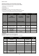
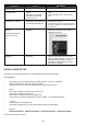
Pump shutting down on
Pump Protection
• Fault in protection sensor • Replace or adjust sensor
Controller powers on and
off continuously
• Voltage being applied to the
Inputs.
• Excessive current being
drawn from the external
pressure sensor
• Make sure that the Inputs are Voltage
Free
• Check external sensor current 100mA
max.
Can’t tune the set point
above/Below a number
• The set point must be
between the Cut In pressure
and the High Pressure limit
• Adjust HP limit or Cut In pressure to allow
the Set point to move
• Check Set Point 2 & 3 to make sure that
they are not above HP Limit or below Cut
In pressures
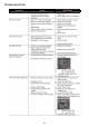
System Displays wont
initialise
Loading Data message
cycles continuously
• System needs to be
initialised.
• Press the “Commissioning Button” on the
PCB whilst powering up the system to
initialise the program
•
System Pressure not
displaying
• Analogue circuits not
functional
• There are 2 LED’s located on the front
top right of the PCB. One is for Power
which should be flashing – the other is for
indication that the analogue circuit is
operational. Solid light means OK- No
light means inoperative.
PROBLEM CAUSE SOLUTION
INSTALLATION NOTES
Here are some “GOLDEN RULES” in site installation that should be followed.
Site Installation
• Select the site most shaded and out of direct sunlight. Heat is a VSD killer.
• Allow the airow from the fans to be unimpeded.
• Always connect the motor earth directly to the earth within the VSD.
• Inputs
• Connect the shield to EARTH and one end only.
• Never apply voltage to the Inputs.
• Take care in running inputs for long distances.
• The inputs use a 24VDC signal as the carrier voltage - use compliant sensors.
• Outputs
• 5 amp maximum switching load.
• Check the programming on each output before trying to troubleshoot.
• Start-up
• CHECK ROTATION CHECK ROTATION CHECK ROTATION CHECK ROTATION
All these items are site related