
User Manual

42
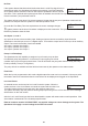
There are 8 main inputs with the Speedman that control external sensing functions.
All inputs are programmable to suit various applications.
They all require VOLTAGE FREE contacts and as such should NOT HAVE ANY VOLTAGE APPLIED.
• All inputs operate on a CLOSED CONTACT for activation. This contact needs to be made between
the input common and the relevant input. There are three terminals for the input Common to allow for multiple
connections.
You can view which inputs are activated by accessing PUMP DATA LOG menu under the “Digital Input State”
screens. See PUMP DATA LOG for more information.
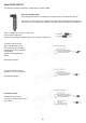
Each Input can now have inverted logic.
Normally if an input is connected via a switch or sensor between the input common and a programmable input
it is deemed to be ON and the input LED will be illuminated.
With inverted logic when an input is activated the controller will read this as OFF but the input LED will be
illuminated to indicate the actual state of the input. Inverted inputs have a number of uses and the main use
would be to provide fail safe activation of an input. Eg. If an programmable input is set to pause the system
on low level, then a normal input would provide an ON signal to pause the system, should that input be
disconnected or broken the system would not shut down resulting in damage to the pumps. If the input is
inverted the oat can be wired to close the input connection for system run & open for system pause. (Fail
Safe)
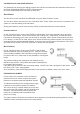
To invert an input, rstly have the required input on the display, press the Enter button and then press the Up
& Down buttons simultaneously, the Input should now show (INV) on the top line. The change it back complete
the same procedure.
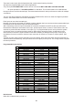
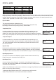
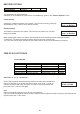
Programmable Input Options
Not Selected
When this is selected the input will not
Option Delay time Duration
1 Not selected Instantaneous Continuous
2 Set Point 2 1 second Continuous
3 Set Point 3 1 second Continuous
4 Set Point 4 1 second Continuous
5 Set Point 5 1 second Continuous
6 Set Point 6 1 second Continuous
7 Set Point 7 1 second Continuous
8 Set Point 8 1 second Continuous
9 Soft Pause 1 second Continuous
10 Soft Pause JP Run 1 second Continuous
11 Emergency Stop Instantaneous Continuous
12 P1 Prot(Pause) Input delay Continuous
13 P2 Prot(Pause) Input delay Continuous
14 Pump 1 Stop Instantaneous Continuous
15 Pump 2 Stop Instantaneous Continuous
16 Pump 1 Manual Run Instantaneous Continuous
17 Pump 2 Manual Run Instantaneous Continuous
18 Fire Mode 1 second Continuous
19 Cycle pumps 1 second Rising edge
20 VFD Fault 1 second Continuous
21 Reset 1 second Rising edge
22 No Flow Input delay Continuous
23 Aux Input 1 Instantaneous Continuous
24 Aux Input 2 Instantaneous Continuous
25 Aux Input 2 Instantaneous Continuous
26 Pump1 Fault(Stop) Pump Fault Delay Continuous
27 Pump2 Fault(Stop) Pump Fault Delay Continuous
28 Flow Pulse Instantaneous Rising edge
29 Low Level Pause 1 second Continuous