
User Manual


29
RR(P) Proportional Output
Displays the proportional component within the PID equation. Proportional is
another name for “Response Rate”
EC(I) Error Correction
Displays the error correction component within the PID equation.
OE(D) Overshoot Elimination
Displays the overshoot elimination component within the PID equation.
These three “Output” display values help in the tuning of the Speedman. Each has a range of -1000 to 1000.
See PID Control for more information.
Low Pressure Shutdown Delay
Time delay for the “Low Pressure Shutdown”.
The range for this is “OFF, 0-250 sec”.
OFF - The system will ignore any low-pressure shutdown commands.
**CAUTION** Low pressure faults can be caused by systems failures. Forcing pumps to run in the presence of
faults can cause damage to pumps and equipment. The Low & High Pressure delay timers are independent of
each other and can be set to suit individual needs.
High Pressure Shutdown Delay
Delays the response “High Pressure Shutdown”.
The range for this is “OFF, 0-250 sec”.
OFF - The system will ignore any high-pressure shutdown commands.
**CAUTION** High pressure faults can be caused by systems failures. Forcing pumps to run in the presence
of faults can cause damage to pumps and equipment. The Low & High Pressure delay timers are independent
of each other and can be set to suit individual needs.
In Delay Timer
The “IN DELAY TIMER” is used to delay the starting of additional pumps.
When the system pressure drops below the “Cut In Pressure” the system starts
the rst pump according to the “restart timer”.
Additional pumps start when called upon after the “In Delay Timer” has elapsed.
This timer is designed to assist in the reduction of Short Cycling by allowing the system to stabilise before
additional pumps are started
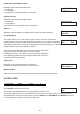
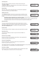
RR(P) EC(I) OE(D)
XXX XXX XXX
LoPressure Delay
XXX Seconds
HiPressure Delay
XXX Seconds
In Delay Timer
XXX Seconds
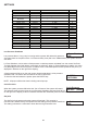
Low Pressure Delay Seconds Off, 0 - 250 120
High Pressure Delay seconds Off, 0 - 250 4
In Delay Timer seconds 0 - 999 4
Out Delay Timer seconds 0 - 999 1
Restart Delay seconds 0 - 999 0
Standby Test Time seconds 0 - 999 10
Boost Hold Time seconds Off, 1 - 250 15
Pump Fault Timer seconds 0 – 250 10
Now Flow Delay seconds 0 – 250 10
Input Delay Timer seconds 0 - 999 120
Pressure Trip Low Delay seconds 0 - 999 0
Pressure Trip High Delay seconds 0 - 999 0
Flow Trip Low Delay seconds 0 - 999 0
Flow Trip High Delay seconds 0 - 999 0
Change Over Delay seconds 0.00 - 10.00 0.30
Stop Time (24hr) HH:MM Disabled, 0:00 - 23:59 Disabled
Start Time (24hr) HH:MM 0:01 -> 00:00 Disabled
TIMING