
User Manual

4
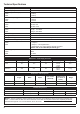
Technical Specications
Input Voltage (ac): 220-240V
Supply Frequency / Phase: 50/60Hz / Single
Maximum Input Current (ac):
M4920
M4921
2.5 Amp
5.0 Amp
Power Consumption @ 230V:
M4920
M4921
0.58 kW
1.15 kW
Output to Cell (dc):
M4920
M4921
22-24V / 9A
24-26V / 25 A
Chlorine Gas Output:
M4920
M4921
59 g/h, 3.12 lbs/d
118 g/h, 6.24 lbs/d
Ideal Salt Range: 4,500 - 6,000 ppm
Cooling: Fan & Heatsinks
Electrolytic Cell Type: Coated Titanium - Reverse Polarity
Maximum water temp (in cell): 45ºC OR 113 ºF
Minimum ow:
M4920
M4921
> 170 lpm *
> 350 lpm * / 95 USgallons/min
* Value based on a 10ppm chlorine level at cell outlet
Please refer to Flow Rate Requirements pg 6
Head loss @ 350lpm
M4920
M4921
8kPa
13.2kPa
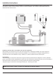
Pipe Connections: 3” / 80mm or 2” / 50mm with adaptors
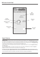
Dimensions – PowerSupply Enclosure
Height Width Depth Mounting Weight
inches 15.7 14.6 8.5
4 Holes:
10.6 W
12.8 H
37 lb
millimeters 400 370 215
4 Holes:
270 W
325 H
17 kg
Dimensions – Electrolytic Cell
Height Width Depth
Inlet / Outlet
(Actual ID)
Plumbing Holes
(From centre to
centre)
Weight
inches 8.1 16.3 4.9 3.5 11 &
3
/
4
6.6 lb
millimeters 206 415 125 89 294 3 kg
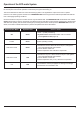
Flow Rate Requirement
Model Nominal Rated Chlorine Gas Output Minimum Flow Rate in Cell
SC Max 77 53 g/h 2.83 lbs/d > 170 lpm > 45 gpm
SC Max 155 106 g/h 5.65 lbs/d > 235 lpm > 63 gpm
NOTE: In certain installations, these minimum ow rates may be insufcient to ll the cell housing completely with
water – in these cases the ow must be increased to ensure that the cell plate surfaces are completely immersed,
otherwise damage will occur and decreased cell life will result.