
User Manual

Single Phase
Three Phase
Daveyrecommendtheuseofoverloadswhichalsohavetheabilitytodetect“singlephasing”or“droppedphase”
conditionsinthepowersupply.
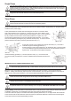
ThreephaseMukmovamodelshavebeendesignedtoallowforconnectioneither
sideoftheCapacitorCover(marked“A”ingureone)onthemotor.(NOTE:Three
phasemotorsdonothavecapacitorsttedintheCapacitorCover).Thisisachieved
bywayofeitherofthetwo19mmaccessholes(marked“B”ingureone).The
accessholesaredesignedtoacceptmoststandardcablegrommets.Theunused
holecanbesealedbyinsertingtheplugenclosedwiththepump.Toconnectathree
phasePressurePumpstartbyremovingtheTerminalCover(“C”).
Ashortfourcoreex(“D”)isttedfromthemotorterminals(“E”).Thisleadis
insertedthroughtheblankinggrommet(“F”).
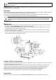
Pressureswitchorothercontrolleads(“G”)canbettedaswell.Incomingpower
(“H”)canbettedthroughthepreferredaccesshole,andterminatedasshownin
FigureThree.Aterminationkitisavailableifrequired.
Inserttheblankinggrommet(“F”)intothecapacitorcover(“A”).Fixtheshortlead
(“D”)intothepathprovidedinthenon-driveendshieldandreplacetheterminalcover
(“C”).
IMPORTANT NOTE: THREE PHASE MODELS ONLY
Whentheunitisconnectedandoperatingthephasebalanceshouldbechecked.Thisshouldbewithin5%
variation.“Rolling”theleadsmayhelptoimproveasmallunbalance,butmajorphaseunbalancewillusuallybe
attributedtoaninputpowerunbalance.Thismustbeaddressedbeforethepumpisused.
Suction Piping-Asthispumpdoesnothaveaxedcolumn,itmaybeusedonawidevarietyofcollectionpitswithout
modication.Furthermore,byusingexiblesuctionpipe,thepitmaybealmostfullyemptied.
Thesuctioninlettothepumpis2
1
/
2
”BSPfemaleandforoptimumperformance,2
1
/
2
”orlargersmoothborereinforced
suctionhoseshouldbeused.Maximumsuctionliftofthepumpshouldbelimitedto6metres(20ft)andthelengthof
suctionpipeshouldnotexceedapproximately8metres.
Before nalising wiring connections, check that motor rotates in direction of arrow (clockwise when shaft
is viewed from wiring connection end). To alter rotation, change any two power leads at motor terminals.
Power connections and wiring must be carried out by an Authorised Electrician.
A registered electrician is required to directly wire in the pump. EXTENSION LEADS MUST NOT BE USED.
The single phase 240/480V motor on this pump is tted with an in-built 240V thermal overload switch located under the
terminal cover on the end of the motor. For 480V operation the terminal connections must be changed as per the wiring
diagram included in the capacitor housing. A 480V overload and tment kit is supplied with the pump. This overload is
tted into the endshield just above the terminal block.
The three phase 415V TEFC motor on this pump must have a contactor wired in which has correctly rated quick trip (M10)
thermal overloads, otherwise any failure will not be the responsibility of Davey.
Single phase units should be restricted to no more than 20 starts per hour.
Note: Minimum three phase voltage supply at the motor must not fall below 374 volts, otherwise motor
damage may result which is not claimable under Guarantee.