
Manual


6
•Page5•
Once the salt level in the pool is correct the unit may be switched on. Set Sanitiser Output to Max (100%).
The STAND - BY indicator will be On and no Cell Output will be seen for approx 30 seconds, this allows the
pumpandltertoprimeandtheCellHousingtollwithwater.Afterthisstart-updelay,thedisplayshould
show100(ESRModels(+/-2),unlessinWinter Modewhereitwilldisplay85(ESRModels(+/-2).Atthis
point both Operation LED’s should be Green; if not there may be a problem. (Refer table).
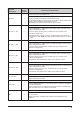
DISPLAY / INDICATOR LED 1 LED 2 REASON / ACTION
STAND – BY ON Green Green
1.Start-updelayfunctioning.
2. Sanitiser Output set below max.
Cell is turned off. (Refer Sanitiser Output
page 7)
FLOW
STAND – BY ON
Green Green
1. Gas detected. Check pump/pipes for damage
2. Gas sensor not connected to cell.
FLUCTUATING
AROUND 100
Green Green System operating normally.
Green Red
1. Salt level too low. Add salt at a rate of 25kg
per 25,000L.
2.Celliscalcied.Cleancell.
3. Water temperature low. Switch to Winter
Mode.
Red Red
1. Salt level below minimum. Add Salt.
2.Celliscalcied.Cleancell.
3. Water temperature very cold. Switch to
Winter Mode. Continued operation may
cause damage to system – Consult dealer for
problemrectication.
PLEASE NOTE: When Winter Mode switch is On Unit will operate similar to above except Display will
uctuatearound85.(ReferWinterModepage8).
AM
6
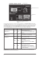
CONTROL PANEL LAYOUT
OPTIONAL POOL LIGHT
SWITCH
SELECTOR SWITCH
TIME CLOCK
SANITISER OUTPUT DIAL
WINTER MODE SWITCH
OPERATION LED’S