
Owner manual


~ 4 ~
Installation
All motors must be installed in such a manner as
to ensure the air intake is not obstructed. Refer to
dimension “BL” in the cooling section of this catalogue.
Bed plates or slide rails should be rmly xed to a solid,
level foundation to ensure the motor remains rigid and
vibration free. Shims or packers (if required) must be of
adequate size and placed adjacent to and between base
xings. Protective transport coatings on shafts and/or
anges must be removed prior to connection to the
driven load.
Coupling Drive / Service
In tting couplings or pulleys to the motor shaft, care
must be taken to ensure the roller/ball bearings are not
damaged. Tapped holes are provided in shaft extensions
to assist in the tment of couplings and/or pulleys. Under
no circumstances should couplings and/or pulleys be
impact driven onto the shaft. Couplings or pulleys should
be independently balanced with a half key.
Alignment / Service
Great care must be taken in aligning the complete unit,
since misalignment can cause rapid deterioration of
bearings and lead to other mechanical failures due to
the stress produced. After nal tightening of foundation
bolts, machine alignment should be rechecked as bed
plates could distort. No end thrust should be applied to
the motor without express approval.
Operation
Standard motors are designed for a 415 volt (±5% ) 3
phase, 50 Hertz supply. Use of standard motors on
other supply systems should be veried with our ofce
prior to installation. All units are S1 rated to AS1359 and
associated standards, for operation below 1000 metres
at a maximum ambient temperature of 40°C.
For operation in conditions other than that above please
contact Davey.
Electric motor starting imposes severe thermal stress on
the motor, the frequency of starting should be minimized
to ensure optimum machine life.
MOTOR OPERATION AND MAINTENANCE
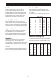
Number of Starts per hour
The number of starts per hour is dependant on the
inertia of the driven load and the load torque demand.
A guide to generally acceptable starts per hour would be
as per table.
For greater number of starts per hour, please contact
Davey.
Starts per hour
Frame 2 pole 4 pole 6 pole 8 pole
71 - 40 - -
80 20 40 40 -
90 16 30 40 -
100 16 30 40 40
112 16 30 40 40
132 10 20 25 25
160 10 20 25 25
180 8 15 20 20
200 6 12 12 12
225 5 10 10 10
250 4 8 8 8
280 3 6 6 6
315 3 4 4 4
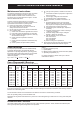
Permitted Starting Time
In respect to the temperature rise of the motor, starting
time (i.e., from rest to operational speed) should not
exceed the time indicated in the following table. Motor
must be allowed to cool prior to each start.
Maximum starting time (sec)
Starting
Frame Method 2 pole 4 pole 6 pole 8 pole
71 D.O.L. - 26 - -
80 D.O.L. 15 26 40 -
90 D.O.L. 10 15 25 -
100 D.O.L. 12 13 18 40
112 D.O.L. 10 10 18 35
132 D.O.L. 14 12 12 25
160-355 D.O.L. 15 15 20 20
160-355 star-delta 45 45 60 60