
User's Manual


Chapter 3
I
n
s
t
a
ll
a
t
i
o
n
ThischapterdescribeshowtoinstalltheOM2P‐LC/OM2P‐HS.ItalsodescribestheOM2P‐LC/OM2P‐
HSLEDs.
Onlyexperiencedinstallationprofessionalswhoarefamiliarwithlocalbuildingandsafety
codesand,whereverapplicable,arelicensedbytheappropriategovernmentregulatoryauthorities
shouldinstalltheOM2P‐LC/OM2P‐HS .
3.1Pre‐installationGuidelines
Selecttheoptimallocationsfortheequipmentusingthefollowingguidelines:
- TheOM2P‐LC/OM2P‐HS shouldbemountedona1"‐4"pole.Itslocationshouldenableeas y
accesstotheunitanditsconnectorsforinstallationandtesting.
- Thehighertheplacementoftheantenna,thebettertheachievablelinkquality.
- Theantennashouldbeinstalledtoprovideadirect,ornearlineofsightwiththeBaseStation
antenna.TheantennashouldbealignedtofacethegeneraldirectionoftheBaseStation.
3.2InstallingtheOM2P‐LC/OM2P‐HS
ToinstalltheOM2P‐LC/OM2P‐HS,usethefollowingproceduretomountthedeviceonapole
andref ertothefigurebelow.
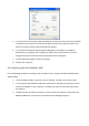
1.ThebottomoftheOM2P‐LC/OM2P‐HSisamovablecover.Grabthecoverandpullit
backhardtoremovethecover.
2. InsertastandardEthernetcableintotheRJ‐45portlabeledMAINL
A
N
.
3. SlidethecoverbacktosealthebottomoftheOM2P‐LC/OM2P‐HS.
4. RemovethepowercordandPoEinjectorfromtheboxandplugthepowercordintothe
DCportofthePoEinjector.
OnlyusethepoweradaptersuppliedwiththeOM2P‐LC/OM2P‐HS.Usingadifferent
poweradaptermightdamagetheOM2P‐LC/OM2P‐HS.
5. PlugtheothersideoftheEthernetcableinstep3intothePoEportofthePoEinjector.
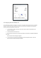
Whenyoufinishstep5,theinstallationwillresemblethefollowingpicture.
6. TurnovertheOM2P‐LC/OM2P‐HS.Theninsertthemaststrapthroughthemiddleholeof
theOM2P‐LC/OM2P‐HS.
Useascrewdrivertounlockthepole‐mountingringputtingitthroughtheOM2P‐
LC/OM2P‐HS.
7. MounttheEOA200securelytothepolebylockingthestraptightly.
Thiscompletestheinstallationprocedure.