
Service manual


FRONT
AXLE
FRONT
SUSPENSION
2
Install
dust
seal
on
knuckle
spindle
support
3
Coincide
direction
of
notch
for
cotter
pin
on
fulcrum
pin
with
direction
of
pin
hole
of
knuckle
spindle
support
and
drive
fulcrum
pin
into
knuckle
spindle
support
with
a
copper
or
lead
hammer
Insert
cotter
pin
into
hole
tighten
lock
nut
Tightening
torque
0
4
to
0
6
kg
m
2 9
to
43
ft
Ib
4r
t
a
Fig
FA
Z8
Installing
fulcrum
pin
4
Screw
bushings
in
both
sides
manually
and
tempora
rily
so
that
knuckle
spindle
support
is
in
the
center
of
lower
link
and
retighten
them
to
the
specified
tightening
torque
Make
sure
that knuckle
spindle
and
lower link
angle
is
76
50
Make
sure
again
that
knuckle
spindle
support
is
in
the
center
of
lower
link
TIlls
operation
can
be
performed
easily
by
removing
f1ller
plug
Tightening
torque
24
to
25
kg m
I73
5
to
180
8
ft
Ib
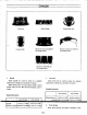
Unit
mm
inl
9
05
to
11
05
0
3563
to
0
4350
36
5 9
05
to
11
05
1
437
0
3563
to
0
4350
Fig
FA
Z9
Installing
screw
bushing
5
Remove
f1ller
plug
install
grease
nipple
and
inject
grease
until
grease
comes
out
from
dust
cover
Reinstall
f1l1er
plug
6
Upon
installation
make
sure
that
fulcrum
pin
operates
smoothly
Operating
resistance
Less
than
0
5
kg
m
3 6
ft
Ib
7
Install
upper
link
bushing
on
the
upper
end
of
knuckle
spindle
support
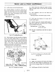
8 Install
the
upper
end
of
knuckle
spindle
support
on
upper
link
arrange
them
to
condition
shown
in
Figure
FA
30
and
tighten
fulcrum
bolt
Tightening
torque
4
7
to
5
2
kg
m
34
0
to
37 6
ft
Ib
Note
Be
sure
to
install
fulcrum
bolt
from
rear
side
of
vehicle
l
j
@
4
54
5
mm
2
146
in
Fig
FA
30
Assembled
posture
of
knuckle
spindle
and
upper
link
5
Tension
rod
I
Tighten
nut
on
the
rear
end
of
tension
rod
to
obtain
r
an
extent
that
rubber
bushings
are
compressed
into
33
4
mm
1
3IS
in as
shown
n
Figure
FA
31
and
tighten
lock
f
nut
2
Install
tension
rod
bracket
on
frame
bracket
fA
15