
Service manual


1
CHASSIS
Reinstallation
1
Lower
link
bushing
I
When
collar
interior
of
lower
link
mounting
bracket
along
which
lower
link
bushing
is
inserted
and
bushing
exterior
are
rusted
remove
rust
with
emery
paper
2
Apply
a
special
tool
ST36070000
used
for
disassembly
to
lower
link
bushing
tap
it
evenly
with
a
hammer
and
fit
lower
link
bushing
to
lower
link
mounting
braclwt
r
0
u
r
r
I
Ie
6
i
t
r
r
I
v
I
j
l
Fig
FA
25
Fitting
IoweT
link
bushing
2
Lower
link
I
Install
torque
arm
on
lower
link
T
gh
I
terung
torque
Arm
head
Serration
boss
2
5
to
3
1
kg
m
18
1
to
22
4
Ib
ft
0
8
to
1
2
kg
m
5 8
to
8
7Ib
ft
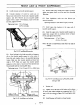
2
InStall
lower
link
on
lower
link
mounting
bracket
and
tighten
lower
link
spindle
nut
at
the
position
of
lower
link
shown
in
Fig
FA
26
Fig
FA
26
Installing
10
link
FA
14
Tightening
torque
85
to
95
kg
m
61
5
to
68
7Ib
ft
3
Upper
link
I
Tighten
screw
bushing
on
upper
link
Install
grease
seal
and
dust
cover
Tightening
torque
24
to
25
kg
m
173
5
to
180
8Ib
ft
2
Fill
screw
bushing
indicated
by
asterisk
in
Fig
F
A
27
fitted
to
upper
link
with
multi
purpose
grease
MIL
G2108
or
10924
Apply
grease
to
thread
on
bushing
interior
and
thread
on
upper
link
spindle
suffici
ently
62
5
2
4611
44
6
U561
Unit
mm
inl
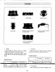
Fig
FA
2
Upper
link
and
up
Unk
spindle
3
Screw
front
and
rear
links
against
upper
link
spindle
in
the
same
length
so
that
opening
width
A
is
44
6
mm
1
756
in
standard
dimension
When
screwing
recommend
fIller
plug
be
removed
4
Upon
installation
make
sure
to
operate
upper
link
spindle
smoothly
Operating
resistance
Less
than
05
kg
m
3 6 ft
lb
5
Remove
filler
plug
install
grease
nipple
and
inject
grease
until
grease
comes
out
from
dust
cover
Reinstall
filler
plug
6 Install
upper
link
spindle
on
upper
link
mounting
bracket
Be
sure
to
use
the
same
camber shims
which
were
used
before
di
embly
I
Apply
multi
i
urpose
grease
to
thread
on
fulcrum
pin
imd
thread
on
screw
bushing
interior
sufficiently
Grease
screw
bushing
sufficiently