
Service manual


FRONT
AXLE
FRONT
SUSPENSION
U
or
it
does
not
rotate
smootWy
or
noise
occurs
7
Spindle
nut
Repair
or
replace
when
thread
is
damaged
Reinstallation
Reinstall
front
axle
in
reverse
sequence
to
removal
by
noting
the
following
matters
Moreover
when
installing
front
axle
lightly
apply
multi
purpose
grease
MIL
G2108
or
10924
to
sliding
parts
I
When
replacing
king
pin
and
bushing
I
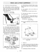
Install
bushing
carefully
by
the
use
of
a
special
tool
ST35380000
so
that
grease
groove
toward
circumferen
tial
direction
is
in
upper
side
and
bushing
joint
is
faced
rearward
Grease
groove
Upper
side
Lower
side
Fig
FA
8
King
pin
bushing
2
Remove
grease
nipple
and
drill
grease
hole
on
bushing
through
threaded
grease
nipple
hole
Drilling
diameter
Approximately
3
mm
0
1181
in
When
grease
hole
is
drilled
thoroughly
remove
metal
particles
and
bur
3
Ream
the
inside
of
bushing
to
standard
value
by
the
use
of
king
pin
bushing
reamer
special
tool
HT56802000
Perform
reaming
from
both
upper
and
lower
bushings
When
reaming
upper
side
utilize
lower
side
as
reaming
guide
and
when
reaming
lower
side
utilize
upper
side
as
reaming
guide
to
align
the
center
line
correctly
Bushing
inner
diameter
when
fitted
20
010
to
20
035
mm
0
7878
to
0
7888
in
2
When
installing
spindle
on
spindle
support
be
sure
to
install
thrust
bearing
to
face
covered side
upward
3
Selecting
spindle
shim
I
Jack
up
the
bottom
of
spindle
slightly
measure
clearance
by
means
of
a
filler
gauge
and
select
proper
spindle
shims
to
obtain
the
correct
clearance
Standard
clearance
0
04
mm
0
0016
in
or
less
Spindle
shim
Part
number
Thickness
mm
in
40032
25660
0
075
0
0030
40033
25660
0
25
0
0098
40034
25660
0
75 0
0295
2
When
king
pin
is
filled
make
sure
to
operate
smoothly
When
turning
resistance
exceeds
standard
value
readjust
shim
and
check
bushing
and
king
pin
if
neces
sary
King
pin
turning
resistance
15
kg
cm
13
in
Ib
4
Install
plug
after
applying
seal
n
its
circumference
and
caulk
three
positions
around
spindle
by
punch
5
Install
bearing
outer
race
FA