G25AMK005 G25AMK005 GUARDIAN 110W MOBILE RADIO TECHNICAL MANUAL Datron World Communications Inc. Manual Part No. G25AMK005 Release Date: May 2002 Revision: A 3030 Enterprise Court Vista, CA 92083, USA Phone: (760)597-1500 Fax: (760)597-1510 E-mail: sales@dtwc.com www.dtwc.
2000 Datron World Communications Inc. All Rights Reserved. GuardianTM Technical Manual for use with the Guardian 110W mobile radio. This manual, as well as the software described in it, are furnished under license and may only be used in accordance with the terms of such license. This manual is furnished for informational use only, is subject to change without notice, and should not be construed as a commitment by Datron World Communications Inc.
NOTICE TO USER WARNING! Maintain a distance of at least 3 feet (1 meter) between the antenna and people. To satisfy RF exposure compliance, you, as a qualified user of this radio device must control the exposure conditions of bystanders to ensure the minimum distance is maintained between the antenna and nearby persons. The operation of this transmitter must satisfy the requirements of the Occupational/Controlled Exposure Environment for work-related use.
CONTENTS CHAPTER 1: 1.1 1.2 1.3 GENERAL INFORMATION ................................................................................................. 1-1 SCOPE ......................................................................................................................................................... 1-1 GENERAL DESCRIPTION .............................................................................................................................. 1-1 PERFORMANCE SPECIFICATIONS ..............
Self-Test on Power-Up....................................................................................................................... 3-2 3.1.5 3.1.6 Flash Software Upgrades ................................................................................................................... 3-2 3.1.7 Voice Coder/Decoder (VOCODER) .................................................................................................. 3-2 3.2 RADIO CONTROL SOFTWARE .............................................
Radio Power Up ................................................................................................................................. 4-2 Choose a Channel............................................................................................................................... 4-2 Transmit a Voice Message ................................................................................................................. 4-2 Receive a Voice Message.................................................
CHAPTER 1: GENERAL INFORMATION 1.1 Scope This manual provides technical information for the Guardian 110 Watt mobile radio system.. This chapter gives a general description and provides a system block diagram. Chapters 2 and 3 provided detailed theory of operation for hardware and software portions of the radio. Chapter 4 provides general operation of the radio. Chapter 5 is the physical description of the radio components and the available accessories.
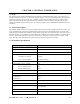
Model Designation Guardian VHF Mobile Radio Receiver (Measurements per TIA/EIA 603 Standards) Sensitivity Digital Mode: 5% BER -116 dBm or greater Analog Mode: 12 dB SINAD Spurious -70 dB Intermodulation -70 dB Audio Output Power 10W, 4Ω external, 5W, 8Ω internal speaker Audio Distortion (at 1000 Hz) 3% Frequency Stability (-30° to 60°C) ± 1 ppm Maximum Frequency Separation Full-band split Transmitter (Measurements per TIA/EIA 603 Standards) RF Power Output 25W to 110W, adjustable Spurious
CHAPTER 2: HARDWARE THEORY OF OPERATION 2.1 Introduction The Control Module contains the Receiver Exciter Control Module (RECM), Audio amplifier board, Interface board, and display and keypad assemblies. The RECM is a shielded assembly containing the transceiver and all control and signal processing hardware and firmware, except the RF and audio power amplifiers. The trunk-mounted RF power amplifier contains a single PC assembly. Schematics for all the boards are located in the back of the manual. 2.
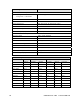
Specification Maximum Frequency Separation DES Encryption Encryption Keys Code Key Generator SBCF Analog DES Encryption Description Full bandwidth 16 External Standard feature Environmental Specifications MIL-STD-810F Test Low Pressure (Altitude) High Temperature Low Temperature Temperature Shock Solar Radiation (Sunshine) Humidity Salt Fog Sand and Dust Vibration Shock Standard Accessories 5W Internal Speaker Palm Microphone Mounting Bracket 14 ft Power Cable Method/Procedure 500.4/II 501.4/I, II 502.
Ignition and Emergency Switch System Control and Programming Speaker out Fused DC Power DB25 DB9 RECM PA control DTMF control Front panel interface (LCD,Keypad and switches) MIC connector Control Head Coax Control Cable Fused DC Cable DC connector Power ON/OFF and R/T switches Control In/Out T AMP Power spliter AMP Filter& combiner T Antenna Connection R R output power control monitor power sensor Mounted Power Amplifier Figure 2-1: Interconnect Block Diagram GUARDIAN VHF 110W M
2.4 RECM Control Hardware Theory of Operation 2.4.1 Control Logic The control logic interfaces to the keypad logic, transceiver, internal audio, and Motherboard. The control logic implements the main radio control function and all the baseband signal processing. TCVR Module DB25 Accessory Connector Keypad Board and Front Panel Interface Grey areas connect through the 80-pin connector on the Motherboard. Power Supply Figure 2-2: Guardian Control Logic 2.4.1.
2.4.1.2 On/Off Switching The main continuous supply 10V control is passed through a front panel on/off switch to generate 10V SW from the main radio supply. In normal operation the on/off switching is controlled by the radio on/off rotary switch by the control /RADON. Once switched on the main controller can hold the radio on by setting PWRHOLD. In addition to the radio rotary on/off switch, the on/off switching can be controlled by the external line /RADOFF via the accessory connector.
2.4.1.5 3.3V Linear Logic Supply The output from the 4.5V switch mode power supply is passed through 3.3V linear power supplies to remove any remaining power supply switching noise on the main logic supply. One 3.3V supply is used for control logic, the other 3.3V, 50 mA supply is used for control logic analog circuitry. 2.4.1.6 Reset Generator This circuit uses a MPU supervisory device (MAX825) to generate a reset pulse of at least 140 ms whenever the 3.3V logic supply drops below 3.08V.
LCDA0: LCD controller A0 command/ data select LCDCS: LCD chip select SCL: I2C and synthesizer clock DACSDA: Transceiver serial data, synthesizer, DAC, S-R SYNTHENA: Synthesizer framing pulse DACENA: DAC framing pulse SRENA: S-R framing pulse /DINT: Interrupt to DSP from H8 /RESO: Watchdog output from H8 2.4.1.
2.4.6 FPGA The control logic uses an Altera 8282 FPGA device to provide a flexible serial data routing function, I/O expansion for H8 and DSP, clock generation, data multiplexing, and to absorb discrete logic functions. The synchronous serial bus routing function involves routing the synchronous serial port of H8 either to the keypad and LCD, or to the I/O expansion in the FPGA. High-order address pins from H8 control this routing and a FPGA dummy write with dedicated FPGA chip select from H8.
2.4.14 Test Interface The test interface provides the following functions: Joint test action group (JTAG) connector access for board test and Flash boot sector programming Board reset and control access Board power supply and on-off switching access H8 serial debug port access 2.4.15 LED The control logic incorporates a 3-color LED used for status information. It is controlled by the FPGA to show red, green, or off. It is optically coupled to the top face of the radio by a light pipe.
2.5.1.3 PIN Diode Switch The antenna PIN diode switch is made up of CR7, CR8, CR9, CR10, and other associated components. This switch is a four-port design. The four ports are antenna 1 (TOP RF), antenna 2 (SIDE RF), receive, and transmit. Receive and transmit ports can be switched to only one of the two antenna ports. Transmit signals are routed from the transmit/receive PIN diode switch (to be discussed in the following paragraph) to the antenna port.
There are two 45 MHz IF amplifier circuits. The first (Q2, T2, etc.) utilizes loss-less feedback to deliver reasonable gain, low-noise figure, and a high third order intercept point simultaneously. Typical gain is 10.5 dB for the first IF amplifier. There are two crystal BPFs and a second 45 MHz IF amplifier. The BPFs provide attenuation for the adjacent and alternate channels, and also for the second image response. FL1 is a four-pole crystal filter with a 20 kHz bandwidth centered at 45 MHz.
U22 is the reference oscillator temperature sensor used to monitor the temperature near Y2. Its output is labeled XTALTEMP on the schematic diagram. This line is normally monitored by the microprocessor so the reference oscillator can be adjusted for drift due to changes in temperature. 2.5.2.2 Receive/Transmit VCOs and Buffer Amplifiers The receive VCO operates from 181 to 219 MHz since high side LO injection is used and the first IF is 45 MHz. The transmit VCO operates from 136 to 174 MHz.
2.5.3 Digital/Analog Control Digital/analog control is shown on page 1 of the RECM schematic. The transceiver is fitted with an EEPROM (U15). The IC is used to store calibration and curve fit data, which is needed when the transceiver is configured with the Guardian radio. Each transceiver has its calibration and curve fit data stored within the EEPROM. The calibration and curve fit data is written to the EEPROM at the successful conclusion of level 2 testing.
configured for a voltage gain of 2. The outputs at U2-1 and U6-1, labeled PABIAS1 and PABIAS2 respectively, are then routed to the gates of the power transistors. The correct DAC values for the bias current are stored in the EEPROM (U15). The correct DAC value is obtained and stored in the EEPROM during the power amplifier bias calibration procedure at level 2 testing.
2.6.2.1 Voltage Regulator and 7.8V On/Off Switch Linear regulator U5 provides +7.8V to the RF power control circuitry and to the other two PC assemblies in the control head. The regulator is powered via Q10 body diode at all time. When the unit is turned off all the circuits are disconnected from power except the transceiver in the control head. The transceiver in this case is in the off state. The power consumption in this case is less than 2 mA powering the boat backup memory circuits. 2.6.
2.6.6 PA ON/OFF Control (Bypass Mode) It is possible to operate the system not utilizing the PA (PA in by pass mode.) This is done by turning on control head on with the PTT depressed. An orange TX light indicates to the user that he is operating in by pass mode. In this mode, output power is about 1dB lower that the nominal levels delivered from the transceiver, as indicated in the table above. In normal mode, Q16 conducts at start-up, causing Q14 to conduct, which keeps Q15 off.
2.7 Display Board The Display board consists of a seven-switch keypad and an LCD module with integrated LED blue backlight. The board is heatstaked onto the plastic front panel, forming a permanent assembly. Electrical connections are made to the Interface board via a 20-pin connector (J13). The radio display module is a full graphics 80x32 pixels LCD, requiring a temperature compensated differential driving voltage of about 12V and a 1/6 bias, 1/32 duty cycle driving scheme.
2.7.1 Control Logic Interface The signals on this interface need not be filtered, but are protected from short circuits to ground. All logic signals are at 0 to 3V Complimentary Metal-Oxide Semiconductor (CMOS) levels at the interface. The interface carries the following functions: • • • • • • • • • • • • • 10V Control Ground /RADON Switched 10V Supply Reset AVR Clock Serial Data Clock Serial Data Input Serial Data Output Key Interrupt LCD Chip Select LCD A0 (data\command select) Keypad Chip Select 2.7.
PTT processing: In normal operation, a PTT switch closure causes Q2 to conduct, which in turn causes Q7 to conduct. This signal is distributed to the rest of the radio as the PTT signal. When a DTMF button is depressed, the transceiver automatically transmits this tone. PTT lockout: To prevent transmission of DTMF tone during programming, a latch circuit is provided to lockout PTT. When the ENTER button is pressed the PTT signals is disabled by a latches circuit.
CHAPTER 3: SOFTWARE THEORY OF OPERATION 3.1 Functional System Operation 3.1.1 General All control and channel software is resident in the RECM. 3.1.
3.1.3 Architecture A single digital signal processor (DSP) handles all signal-processing functions. An H8 microcontroller is used to control the user interface and implement other radio control functions. All references to signal names relate to the Receiver/Exciter/Control Module (RECM). Functionality partitioning is shown in Figure 1-1. 3.1.4 Board Identification The control logic stores an electronic serial number and modification status within nonvolatile storage on the board. 3.1.
The DSP pages-in different program images from the Flash for different modes of operation. Typically one image is used for receive and standby modes, but a new image is needed for transmit and key management operations. The DSP can interrupt the H8 controller, and then pass data over the host port back to H8.
Mode TX/RX (SR bit 7) STD/SIDE (SR bit 8) CTX (FPGA output) 3.2.3.2 Description Set in active transmit mode, front end TX/RX control Set to use radio antenna, reset to use accessory connector RF port Set in active transmit mode to enable the RF power amplifier Frequency Control The frequency of operation in both transmit and receive is controlled by the H8 setting in the synthesizer through the serial bus.
3.2.3.8 Receiver Scanning In some scanning modes it is necessary for the radio to scan a number of channels looking for traffic, as controlled by the H8 software. The basic requirement is to change the synthesizer frequency, RXVTF, synthesizer tune DAC, and to resume searching on the new frequency. The DSP may have to be informed of new traffic settings on which to search, for each new frequency. Scanning is interrupted when the DSP detects a signal of interest. 3.2.
3.2.6.1 Audio and Power Supply Unit (PSU) Driver A serial interface driver controls the output bits of a serial-to-parallel output shift register in the FPGA. Clock and data source for this shift register is the same serial port used for the user interface serial bus, but data is directed to the shift register using high-order H8 address lines. 3.2.6.2 Transceiver Serial Bus Driver A serial interface driver controls the transceiver shift register, DAC, and synthesizer.
Project 25 Voice Module VOICE Audio Processing Module Audio CODEC DTMF Tones CVSD DES Module Analog FM Module Transceiver Modulation Module Figure 3-2: Transmit DSP Chain 3.3.1.4 CVSD DES Module Audio data from the Audio Processing module is sent to the audio circular buffer. The sample rate is increased from 8 ksps to 12 ksps. The CVSD encodes the data and sends it to the transmit CVSD audio circular buffer.
3.3.1.7 Transceiver Interface The transceiver DAC has four output ports, two of which modulate the carrier. One of the two channels maintains carrier frequency accuracy. On transmit channel changes, the controller provides the DSP with two fractional values used to scale the two signals output from the DAC. The controller provides the DSP with an additional integer value at one second intervals, and is added to one of the DAC output signals to control carrier frequency accuracy.
filter is applied to the IQ data stream. Calculating the angular difference between consecutive IQ pairs demodulates the received signal. 3.3.2.2.1 Analog to Digital Converter Because the signal BW is much less than the 455 kHz carrier frequency, the ADC sub-samples the 455 kHz IF producing a frequency translation as part of the sampling process. The ADC sampling rate is 96 ksps. 3.3.2.2.
upper path signal removes the dc component from the upper path signal. Following this, the resulting signal passes through a single-bit quantizer and the output buffered for use by the code removal step. Data extraction and DCS code comparisons are then accomplished. 3.3.2.3.3 CVSD DES Detection Detection of CVSD DES waveform is performed by a secure detection function. This function also recovers the 12 kbps bit stream from the 48 ksps input signal.
3.3.3 DSP Software The program data for the DSP is stored in 64K Flash program blocks. The data is stored as unpacked bytes. The blocks used for the DSP software are dedicated so that selective upgrades of this code only are possible. 3.4 Keypad MPU Software 3.4.1 Overview The keypad microprocessor unit (MPU) provides an indirect interface via the Motherboard to the DTMF keypad and front panel switches. It communicates with the main controller via a synchronous bi-directional serial link. 3.4.
• • • • • • Keypad power up okay Keypad error 1-n Key press 1-16 Key release 1-16 PTT press PTT release Volume switch 1-16 Channel switch 1-16 Toggle switch 1-3 Auxiliary key press 1-3 Emergency key press Controller to keypad Request current switch status Reset and execute BIT test Backlight off/bright/dim LED off/red/green/yellow/flash/flash rate Key press request and interrupt acknowledge LCD data transfers are in blocks of 80 bytes maximum, allowing a pause on the serial interface at least every 100 ms
3.5.3.3 CAI Receive Voice Mode The DSP takes the 9.6 kbps CAI-compatible data stream and framing, and splits out the voice data for passing to the VOCODER. The DSP decodes the link control words so that the host H8 can read the link control fields, and the encryption synchronization information is available to the encryption process. CAI receive processing is initiated by the frame synchronization correlator trigger.
3.5.5 Receive Physical Link Layer This software uses common FM demodulation software, and mode-dependent receiver physical layer software modules. 3.5.5.1 Receive ADC and DAC Interface In receive modes SSI port 1 is used in a duplex manner to allow the ADC to be read continuously at 96 kHz and the DAC written up to 48 ksps for AGC and reference oscillator adjustment. In receive modes, the SSI port is clocked at 1536 kHz from an external clock source, using a 16-bit cycle.
3.5.6.2 CAI Encryption The DSP software uses DES kernel software to implement the CAI encryption of voice traffic as described in TIA/EIA/IS-102.AAAA. The key manager supplies the encryption key. In transmit, the message indicator (MI) vector is passed to data link processing for encoding and transmission. In receive, the data link layer decodes the MI vector, and fly wheeled if decoding fails for up to n frames. 3.5.6.
3.5.10 Hardware Control The DSP software controls the DSP clock rate through the phased locked loop (PLL) output divider. The DSP clock rate is dynamically matched to the mode of operation, in coarse steps for example, between searching and tracking receive modes. The DSP software uses low-current wait modes in pauses between processing to minimize current consumption. The host is also able to request a very low-current idle mode in the DSP. The host releases this mode. 3.6 Controller Software 3.6.
3.6.2.2.1 Interrupt Sources The following interrupt sources are used in H8. Interrupt Source User interface DSP Low dc voltage Timer PC serial port UI serial port Debug serial port Alarm generator Description External interrupt from the keypad External interrupt from the DSP, signal detected, etc.
3.6.2.3.2 Full Start-Up Software If a valid H8 program image exists, the full start-up code executes. This involves initializing RAM, DSP, keypad, user interface, FPGA, transceiver, etc., executing the start-up BIT, and transferring control to the main scheduler. 3.6.2.3.3 FPGA Configure Software At start-up H8 configures the FPGA using data from the main Flash memory and transferring it via a synchronous serial bus to the FPGA. 3.6.2.
3.6.3.1.4 Transceiver EEPROM The radio transceiver has an 8k x 8 serial EEPROM for storing transceiver calibration data. This data is set during production testing for the specific transceiver. The data in this device is essentially constant and is never written to by the main controller. At switch on, contents of the EEPROM are copied into the external RAM; EEPROM is not accessed during normal operation. 3.6.3.2 Data Types The controller software uses a number of different data types. 3.6.3.2.
All transfers and operations on the fill port are cyclic redundancy checked (CRC) and acknowledged. 3.6.4.2.1 Cloning The radio can export channel data to other radios. Data export is initiated by a user interface operation at the exporting radio. The exporting radio emulates a PC programmer during the data transfer. Cloning of keyfill data is not allowed. 3.6.4.2.2 Radio Keyfill The DSP software manages the radio keyfill protocols. 3.6.4.
CHAPTER 4: INSTALLATION, ADJUSTMENT, AND OPERATION 4.1 Radio Configuration 4.1.1 Channels A channel consists of a receive and transmit frequency pair. The radio has a total of 256 selectable channels. Each channel can be programmed for different receive and transmit frequencies, squelch, modulation, encryption, and power. Each channel can have one of possible 16 keys assigned on a channel-by-channel basis. An 8-character alphanumeric label identifies each channel or by its channel number if no text label.
4.3.5 Radio Power Up Turn on the radio using the on/off/volume knob. The radio performs a self-test and sounds a short medium-pitched tone to indicate PASS. Use the switch to set the volume to a comfortable level. Select the desired channel using the channel select switch. The process takes 3 to 5 seconds before the radio is ready for operation. 4.3.6 Choose a Channel The default display shows the current zone and channel. Use the channel select switch to select a different channel in the zone.
CHAPTER 5: RADIO SET AND ACCESSORIES 5.1 System Description The Guardian consists of the following components: • • • • Receiver/Exciter/Control Module (RECM) Front Panel Interface Motherboard Heatsink Assembly For available accessories, contact a Datron Guardian representative. 5.1.1 Mobile Radio The Guardian is a vehicular-mounted transceiver capable of providing secure and non-secure communications over the 136 to 174 MHz RF range.
Receive and Transmit Parameters: Operating frequencies, P25 NAC (digital), talkgroup (digital), squelch mode/value (analog), and shadow channels GLOBAL KEY User (configuration name) User ID P25 Keys and Switches: Auxiliary switch (1-3) function, toggle switch function, and emergency button function Programming Access: Programming enable, and programming password Scan: Revert mode, scan delay, scan reply, and monitor time Transmit: Transmit inhibit/override, and transmit time-out Emergency: Alert mode, dur
5.2.1.6 Programmable Keys Three programmable keys are located on the front panel of the radio.
5.2.2.3 Audible Tones The radio has several audible tones that are activated by states of operation or by radio faults. These tones are described in Chapter 9. 5.2.3 Connectors 5.2.3.1 Accessory Connector The accessory connector is a DB25 connector located on the rear panel of the radio. This connector is used for multiple functions, including PC programming, keyfill, cloning, external speaker, and audio accessory attachment. The pin names and functions are defined in Chapter 10. 5.2.3.
Type Individual Call Description TGID is automatically set to 0000 (hex) and the user ID of the targeted radio is activated within the Project 25 digital transmit signal 5.3.2 Receiver Characteristics 5.3.2.1 Receiver Performance The receiver is capable of demodulating a single-channel FM carrier using either conventional 12.5 kHz FM, 25 kHz FM, C4FM, or compatible quadrature phase shift keying (CQPSK) modulation. The receiver demodulates analog or digital voice and data signals.
5.4.3 Zeroize The radio can be programmed using an optional, external emergency key to zeroize all encryption keys. Using the programming menu, the radio can also zeroize all encryption keys, or selectively zeroize individual encryption keys. The emergency key is programmed using the PC programmer.
CHAPTER 6: SERVICING THE RADIO 6.1 General There are no user serviceable parts in the Guardian radio. Return it for servicing to the manufacturer after requesting an RMA number. Attempts to service the Guardian radio by non-authorized personnel voids the warranty. 6.2 Self-Test at Power Up At radio switch-on, the H8 controller executes a number of tests to confirm correct operation. Any errors are reported to the user through displayed error messages and logged in the Flash.
CHAPTER 7: TROUBLESHOOTING 7.1 Introduction This chapter is included to help qualified service personnel troubleshoot and repair the Guardian radio. If questions or problems arise, contact Datron Technical Support Services Group, Datron World Communications Inc., 3030 Enterprise Court, Vista, CA 92083, or phone (760) 597-3755, or email to: guardianservice@dtwc.com.
7-2 GUARDIAN VHF MOBILE
CHAPTER 8: DEFINITIONS Alert Mode: Display and audio properties are used when the emergency key is pressed. In normal mode, the display flashes EMERGENCY and an audio tone is heard. In silent mode, the display is blank and no audio tone is heard. Analog-to-Digital Converter (ADC): An electronic device for converting data from analog to digital form for use in electronic equipment. Backlight: The light behind the keypad and LCD enables the keys and LCD to be visible in dark conditions.
Priority 2 Scan: Priority-2 channel is sampled in a similar fashion to the priority-1 channel. Activity on the priority-2 channel overrides all other modes except emergency and priority 1. Receive Only Channel: A feature that does not allow outgoing transmissions on the channel. It is used for channels in which transmission is prohibited (i.e., weather channels). If PTT is pressed on a receive-only channel, RX ONLY appears on the display.
CHAPTER 9: SIGNAL TONES Tone Brief low-pitched Signal Key press error Failed power on self-test (POST) Transmit time-out warning Empty channel warning Steady low-pitched Transmit time-out timed out Transmit inhibit Invalid mode Radio locked Brief medium-pitched Repeated medium-pitched Brief high-pitched Repeated high-pitched GUARDIAN VHF Key press Radio passed POST Clear voice received Emergency call state Key error Low dc supply voltage Individual call 110W MOBILE Cause Invalid key pressed Radio
9-2 GUARDIAN VHF MOBILE
CHAPTER 10: 10.1 CONNECTOR PINOUTS Accessory Connector Pins and Functions Pin 1 Signal Name RS232_RXD 2 3 RS232_RTS SERIAL_CLOCK 4 5 RS232_CTS PC_232RXD 6 7 8 9 SQUELCH_INF GND EXTERNAL_SPEAKER_N EXTERNAL_PTT/KID 10 11 7.
10.2 Power Connector Pins and Functions Pin 1 Signal Name BATTERY Description Battery power 2 GROUND Ground 3 IGN_SW Ignition switch 4 EXTERNAL_10W_SPEAKER_N External speaker 5 EXTERNAL+10W_SPEAKER_P External speaker 6 BATTERY Battery power 7 GROUND Ground 8 GROUND Ground 9 EMERGENCY_SWITCH Emergency switch 10.
CHAPTER 11: GUARDIAN VHF 110W MOBILE SCHEMATICS 11-1
J9 1 2 3 4 5 6 7 8 9 10 REV ECN A 02-0128 DESCRIPTION DATE BB RELEASE APPR 02-19-02 E1 V3.3_LCD LCD_RESET_N LCD_DATA_MODE +7.7V C1 .01 C2 LCD_TX LCD_CLOCK LCD_CS_N .01 E2 LCD_BACKLIGHT 080010002 C3 .01 PART OF LCD MODULE 320803 KEYPAD_SCAN_OUT_1 KEYPAD_SCAN_OUT_2 KEYPAD_SCAN_OUT_3 KEYPAD_SCAN_IN_1 P13 1 2 3 4 5 6 7 8 9 10 11 12 13 14 15 16 17 18 19 20 S1 S2 S3 MENU KEY 1 MENU KEY 2 KEYPAD_SCAN_IN_2 V3.
REV EXTERNAL AUDIO AMPLIFIER 10K 47uF,20V 47uF,20V 1nF R13 10k +IN2 OUT2 Vref BS2 3 R16 10k 9 8 R3 --IN1 +IN1 C6 1uF/25V 13 C5 1uF/25V 10k R33 10k BS1 OUT1 6 R4 5 0ohm INT_5W_SPEAKER_P TDA1516BQ 12 R15 EXTERNAL_10W_SPEAKER_N 0ohm 1 4 RR +IN2 OUT2 Vref BS2 GND2 10k RR 2 C4 1uF/25V R14 EXTERNAL_10W_SPEAKER_P 0ohm R5 9 0ohm 8 INT_5W_SPEAKER_N 7 R2 M/SS Vp M/SS 5 GND1 4 R1 200k J2 6 TDA1516BQ 13 C1 1uF/25V C22 47uF,20V 47uF,20V U2 BS1 OUT1 3 R8
REV C27 .01uF DESCRIPTION DATE APPR C38 1nF C62 C63 47uF,20V 47uF,20V 8 Q6 DTA114EKA ECN C15 1uF/25V VCC U3C LM2904 GND 4 C33 Q5 2N7002 DNP R40 DNP 68k 1k R8 0.01ohm-1% LM2904M 5 15K 6 U5A R16 4.99K R73 15K DNP R78 DNP R9 R13 100K 51.1K Q1 TPC8106-H Q17 TPC8106-H Q2 TPC8106-H Q18 TPC8106-H R15 10k U7A LM2904 3 2 RF_IN C54 18pF C95 2.2pF L3 4 RF_OUT C66 .001uF U9 701363 C55 6.
REV ECN DESCRIPTION DATE APPR J2 1 2 3 4 5 6 7 8 9 10 11 12 13 14 15 16 17 18 19 20 RS232_RXD PC_232RXD RS232_RTS SERIAL_CLOCK RS232_CTS RS232_DTR IGN_SW EMERGENCY_SWITCH PC_232TXD RS232_TXD WRU_MONITOR EXTERNAL_MIC_BIAS/KEY EXTERNAL_SPEAKER_P/KLD EXTERNAL_MIC/WE EXTERNAL_PTT/KID EXTERNAL_SPEAKER_N 3.3V E3 PAD 3.3V C20 1uF/16V R17 KEYPAD_SCAN_IN_1 R18 47K Q1 DTA144EK VBAT Q15 2N7002 1M Q8 2N7002 10k J6 1 2 VOLUME_SWITCH_1 10K 3.3V 3.3V C38 DNP Q11 DTA114EKA Q6 2N7002 3.
1 2 3 4 5 REVISIONS ZONE REV 01 DESCRIPTION 02 4.5VSW D36 BAR43S 2 2 1 FL6 BEAD D37 BAR43S 3V3LOGIC CONTROL SIDE A D39 BAR43S R376 3 6,8 7.5VT 3 B.MAAT 6 RADONSW 1 7.5VT 10/10/01 3V3LOGIC D38 CMDSH2-3 2 3V3LOGIC - BOARD SPIN 2 UPDATED 3V3LOGIC XCVR SIDE 3V3LOGIC APPROVED - R374 100K 1% Q49 BSS123 1 2 3 BATTSW 2 100 1% 3 BATTBUS 2 8 7.5VA R385 RSSIMON 2,3 8 BATTSENSE 10 RSSI 1 1 A NOTES: UNLESS OTHERWISE SPECIFIED. 1. INTERPRET DRAWING PER MIL-STD-100. 2.
1 2 3 4 5 3V3LOGIC R505 10 1% 3V3LOGIC RSTVCC 1,3,4,5,6,7,8,9,10,11,12 GND_SIGNAL C482 0.1 uF 10% R506 10K 1% U60 MAX825TEUK 5 /RESO VCC RESET MR RESET 1 /RES 5 3 Q66 2N7002 1 2 3 DSPWD A 3V3LOGIC 2 A GND 3 4 R514 150K 1% R507 10 1% 3V3LOGIC 3V3LOGIC C LKDVRVCC O.P 3 2 C490 100 pF 5% C495 NU 2 A Y R516 182K 1% R518 NU TCXOCTRL 5 DV RINCLK C487 0.01 uF 10% GND VCONT XTALCLK R515 82.5 1% 4 DVROUTCLK DSPCLK 3 R568 82.5 1% NC 1 FPGACLK 5 MPUCLK 1 C485 0.
1 2 3 4 5 1,2,4,5,6,7,8,9,10,11,12 GND_SIGNAL 1,2,7 /XRST 1,2,7 /RESET_JTAG 3V3LOGIC A L79 BEAD R538 33.2K 1% DECOUPLING CAPS MUST BE CLOSE TO DSP VCC PINS A DSPVCC AB0 AB1 AB2 AB3 AB4 AB5 AB6 AB7 AB8 AB9 AB10 AB11 AB12 AB13 AB14 AB15 AB16 AB17 DB0 DB1 DB2 DB3 DB4 DB5 DB6 DB7 DB8 DB9 DB10 DB11 DB12 DB13 DB14 DB15 B 2 DB[0..
1 2 3 4 5 A A 1,2,3,5,6,7,8,9,10,11,12 GND_SIGNAL 3V3ANALOG C463 3900 pF 5% 3V3ANALOG R483 10 1% 1 U57 LMC7101A 365438 R490 15K 1% R491 221K 1% B 41 40 42 11 45 46 44 17 43 36 C469 0.047 uF 10% C472 1.0 uF 20% + C471 2.2 uF 10V D67 BAR43C U56 TLV320 MICGS MICIN DCLKR MICBIAS CLK MICMUTE DOUT EARB FSX EARGS FSR EARA DIN EARMUTE LINSEL PDN TSX/DCLKX VMID AGND C470 0.1 uF 10% 5 EXTMIC 9 4 R488 100K 1% C466 + 15 uF 10% 10V DVCC + C465 0.
1 2 3 1,2,3,4,6,7,8,9,10,11,12 GND_SIGNAL 4 FPGAVCC R565 10K 1% R447 1K 1% R448 10K 1% R446 10 1% L73 BEAD R449 1K 1% C448 0.1 uF 10% R450 1K 1% C451 0.1 uF 10% C450 0.1 uF 10% C449 0.1 uF 10% C452 0.1 uF 10% C453 0.1 uF 10% 5 3V3LOGIC C447 + 2.
1 2 3 4 5 A A LBI 2 3V3ANALOG 7.5VT R421 100 1% U44 LP2980A-3.3 P60 1,8 7.5VT C414 0.1 uF 10% 1 2 3 VIN VOUT 5 GND EN NC 4 C416 0.1 uF 10% C415 + 4.7 uF 10% 10V 1,2,3,4,5,7,8,9,10,11,12 GND_SIGNAL 3V3LOGIC R424 2.00 1% 7.5VT U46 MIC5205 P61 4.5VSW R422 47.5 1% 8 4.5VSW P56 1 C417 0.1 uF 10% 2 3 VIN VOUT 5 P57 2 GND EN NC R423 10 1% D46 CMDSH2-3 U45 LP2980A-3.6 1 2 C423 0.1 uF 10% C418 + 4.7 uF 10% 10V C420 0.1 uF 10% 4 1 3V3CONT 3 VIN VOUT 5 C422 0.
1 2 3 4 5 3V3LOGIC 3V3LED Q50 BSS84TA 2 3 BL_LCD_N 1 R409 1K 1% BL_KP_N 1 A BL_KNOB_N 1 3 A 1 R408 47.5K 1% C410 0.01 uF 10% 3 R413 100K 1% R414 100 1% R415 100K 1% 3 /BK_DIM Q54 2N7002 Q53 MMBT3904 1 C412 0.01 uF 10% R416 100K 1% R417 100 1% 2 1 Q52 MMBT3904 1 C411 0.01 uF 10% 2 R412 1.
1 2 4 5 U36-2 Si4925DY 32675 U36-1 Si4925DY 32675 E1 PAD1 1 BATTERY+ 3 C311 0.1 uF 10% 1 D S D C312 + 15 uF 20V 20% S R298 150K 1% 3 1 TXCTRL 1 2 1 5 7.5VT_XCVR 12 6 R299 150K 1% Q48 2N7002LT1 SS-32550 A R306 0 7.5VA_XCVR 11 2 Q47 2N7002LT1 SS-32550 BATTCTRL D D 3 A R297 150K 1% 3 2 E3 PAD1 BATTSENSE P55 1 G 8 G BATTERY- 7 4 P54 E2 PAD1 C318 0.1 uF 10% C319 0.1 uF 10% R300 150K 1% GND_SIGNAL 1,2,3,4,5,6,7,9,10,11,12 20VCLK 1,11 1,6 7.5VT 1 7.
1 2 3 4 5 7.5VA_XCVR 8,11 7.5VA_XCVR +3.3VRX A A 10,11 +3.3VRX +5VDIG TXVCOMOD 11 11 +5VDIG R169 274K 1% R186 47.5K 1% 1,2,3,4,5,6,7,8,10,11,12 GND_SIGNAL +5VDIG 20V 12 BIT DAC R255 100K 1% +2.5VREF + 3 - 5 1 VDD OUTA OUTB FBA 5 OP 3 3 R252 100K 1% 2 +IP FBB 1 REFOSCMOD 11 U75 V- 4 R254 100K 1% TP24 -IP LM7301 365661 2 20 2 C267 0.1 uF 10% 4 MAX525B 365588 AD1582C 365795 SOT23/3P C544 .033 uF TP U31 U32 +5VDIG R172 90.9K 1% V+ C257 0.
1 2 3 4 5 RF AMPLIFIER +3.3VRX 1st IF AMPLIFIER C1 0.1 uF 10% +3.3VRX R1 10 1% L7 0.39 uH 2% C4 1000 pF 5% L8 7T-AW 3400439-5 R1 D27 SMV1204-136 D4 SMV1204-136 1 2 2 1 R187 100K 1% R9 100K 1% L15 5T-AW 3400439-3 L11 1.2 uH 5% P1 3 1 3 D28 SMV1204-136 2 1 3 2 R12 51.1 1% C5 1000 pF 5% R3 C9 2.7 pF 0.1pF R4 11T R3 2.67K 1% 3 L3 56 nH 2% L2 47 nH 2% L4 100 nH 2% L9 56 nH 2% C11 5.6 pF 0.
1 2 MIC5205 1% 365499 +5VDIG +3.5V VIN 3 VOUT 5 1 ON/OFF 4 + NC GND 2 C120 4.7 uF 10% 10V SS-25122-475-10 VIN 3 C121 1.0 uF 20% 35V ON/OFF + 2 C123 + 4.7 uF 10% 10V SS-25122-475-10 R89 110K 1% GND P13 4 BYP +3.3VRX A P14 5 VOUT C295 0.01 uF 10% TP8 R87 10 1% +3.3VA TP TP 4.5VSW_XCVR 1 1 5 1 TP7 LP2980A-5.0 365413 C118 1.0 uF + 20% 35V 25122-105-35-A 4 U17 U16 7.5VA_XCVR 3 C124 + 4.7 uF 10% 10V R91 200K 1% 10 +3.3VRX A +5VDIG 4.5VSW_XCVR C125 2.
1 2 3 4 SENSOR LOCATED CLOSE TO POWER MODULE 7.5VT_XCVR 8 7.5VT_XCVR +5VTX 4.5VSW_XCVR C216 0.1 uF 10% A U11 8,11 4.5VSW_XCVR LM50B 365437 R191 100 1% +V +3.3VDIG 1 A 5 GND 11 +3.3VDIG 2 OUT PATEMP 1 C540 1000 pF 5% 3 1,2,3,4,5,6,7,8,9,10,11 GND_SIGNAL PRE-DRIVER POWER MODULE 7.5VT_XCVR TXSINK B1 50@100 45270 P39 C331 0.018 uF 10% RF IN C81 2.7 pF .25pF R24 4 MMBR941 32098 P38 R44 475 1% R52 475 1% R57 150 1% C88 0.01 uF 10% C209 6.8 pF .