6Gb/s SATA RAID TB T12-S6.TB - Desktop RM12-S6.TB - Rackmount User Manual Version: 1.
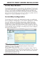
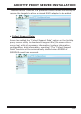
ARCHTTP PROXY SERVER INSTALLATION 5.5 For Mac OS 10.X The ArcHttp proxy server is provided on the software CD delivered with 6Gb/s SATA RAID controller or download from the www.areca. com.tw. The firmware embedded McRAID storage manager can configure and monitor the 6Gb/s SATA RAID controller via ArcHttp proxy server. The Archttp proxy server for Mac pro, please refer to Chapter 4.6 "Driver Installation" for Mac 10.X. 5.
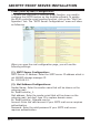
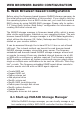
ARCHTTP PROXY SERVER INSTALLATION • Mail (alert by Mail) Configuration: To enable the controller to send the email function, you need to configure the SMTP function on the ArcHttp software. To enable the RAID controller email sending function, click on the “Mail Configuration” link. The "SMTP Server Configurations" menu will show as following: When you open the mail configuration page, you will see the following settings: (1).
ARCHTTP PROXY SERVER INSTALLATION (3). Event Notification Configurations: MailTo Name: Enter the alert receiver name that will be shown on the outgoing mail. Mail Address: Enter the alert receiver mail address. Ex: admin@areca.com.tw. According to your requirement, set the corresponding event level : Disable Event Notification: No event notification will be sent. Urgent Error Notification: Send only urgent events. Serious Error Notification: Send urgent and serious events.
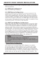
ARCHTTP PROXY SERVER INSTALLATION When you open the SNMP traps configuration page, you will see the following settings: (1). SNMP Trap Configurations Enter the SNMP trap IP address. (2). SNMP System Configurations Community name acts as a password to screen accesses to the SNMP agent of a particular network device. Type the community names of the SNMP agent in this field.
ARCHTTP PROXY SERVER INSTALLATION "Rescan Device" function is a procedure which forces the archttp to rescan the targets to allow a missed RAID adapter to be added. • Collect Support Data: Areca has added the “Collect Support Data” option on the Archttp proxy server utility to download a support file (file name:ctlrxxxxxxx.log) with all necessary information (system information, configuration, disk information, eventlog).
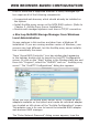
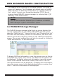
WEB BROWSER-BASED CONFIGURATION 6. Web Browser-based Configuration Before using the firmware-based browser McRAID storage manager, do the initial setup and installation of this product. If you need to boot up the operating system from a RAID volume set, you must first create a RAID volume by using McBIOS RAID manager. Please refer to section 3.3 “Using Quick Volume /Raid Setup” configuration for information on creating this initial volume set.
WEB BROWSER-BASED CONFIGURATION Linux or more and a supported browser. A locally managed system requires all of the following components: • A supported web browser, which should already be installed on the system. • Install ArcHttp proxy server on the SATA RAID system. (Refer to Chapter 5, Archttp Proxy Server Installation) • Remote and managed systems must have a TCP/IP connection.
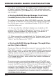
WEB BROWSER-BASED CONFIGURATION User Name and Password. The RAID controller default User Name is “admin” and the Password is “0000”. After entering the user name and password, press Enter key to access the McRAID storage manager. • Start-up McRAID Storage Manager from Linux/ FreeBSD/Solaris/Mac Local Administration To configure the internal 6Gb/s SATA RAID controller. You need to know its IP address. You can find the IP address assigned by the Archttp proxy server installation:Binding IP:[X.X.X.
WEB BROWSER-BASED CONFIGURATION To configure RAID controller on a remote machine, you need to know its IP address. The IP address will default show in McBIOS RAID manager of “Ethernet Configuration” or “System Information” option. Launch your firmware-embedded TCP/IP & web browser-based McRAID storage manager by entering http://[IP Address] in the web browser. Note: You can find controller Ethernet port IP address in McBIOS RAID manager “System Information” option. 6.
WEB BROWSER-BASED CONFIGURATION 6.3 Main Menu The main menu shows all available functions, accessible by clicking on the appropriate link. Individual Category Description Quick Function Create a default configuration, which is based on the number of physical disks installed; it can modify the volume set Capacity, Raid Level, and Stripe Size. Raid Set Functions Create a customized RAID set. Volume Set Functions Create customized volume sets and modify the existed volume sets parameter.
WEB BROWSER-BASED CONFIGURATION Note: In “Quick Create”, your volume set is automatically configured based on the number of disks in your system. Use the “Raid Set Functions” and “Volume Set Functions” if you prefer to customize your volume set, or RAID 30/50/60 volume set. 6.5 Raid Set Functions Use the “Raid Set Function” and “Volume Set Function” if you prefer to customize your volume set.
WEB BROWSER-BASED CONFIGURATION 128 volumes is the default mode for SAS RAID controller, the 16 volumes mode is used for support roaming this raidset to 3Gb/s SATA RAID controllers. The 3Gb/s SATA RAID controller is designed to support up to 16 volumes only. You have to use “Max 16 volumes” on the raidset mode if you plan to roam this raidset between 6Gb/s SATA RAID controller and 3Gb/s SATA RAID controller.
WEB BROWSER-BASED CONFIGURATION Select the “Expand Raid Set” option. If there is an available disk, then the “Select SATA Drives For Raid Set Expansion” screen appears. Select the target RAID set by clicking on the appropriate radio button. Select the target disk by clicking on the appropriate check box. Click on the "Submit" button to start the expansion on the RAID set. The new additional capacity can be utilized by one or more volume sets.
WEB BROWSER-BASED CONFIGURATION 6.5.5 Rename Raid Set The default RAID set name will always appear as “Raid Set #” when it is first created by the controller. The "Rename Raid Set" function is for customer to rename the default RAID set name. To rename a RAID set from a group of RAID sets: (1). Click on the ”Rename Raid Set" link. (2). Click the RAID set check box from the list that you wish to rename. Click the “Submit” button. The following screen appears. Use this option to rename the RAID set name. 6.
WEB BROWSER-BASED CONFIGURATION displayed showing all RAID sets existing on the current controller. Click the RAID set number to activate in the select column. Click on the “Submit” button on the screen to activate the RAID set that had a disk removed (or failed) in the power off state. The 6Gb/s SATA RAID controller will continue to work in degraded mode. 6.5.
WEB BROWSER-BASED CONFIGURATION 6.5.8 Delete Hot Spare Select the target hot spare disk to delete by clicking on the appropriate check box. Click the “Confirm The Operation” check box and click the “Submit” button on the screen to delete the hot spares. 6.5.9 Rescue Raid Set When the system is powered off in the RAID set update/creation period, the configuration possibly could disappear due to this abnormal condition. The “RESCUE” function can recover the missing RAID set information.
WEB BROWSER-BASED CONFIGURATION 6.6 Volume Set Functions A volume set is seen by the host system as a single logical device. It is organized in a RAID level with one or more physical disks. RAID level refers to the level of data performance and protection of a volume set. A volume set capacity can consume all or a portion of the disk capacity available in a RAID set. Multiple volume sets can exist on a group of disks in a RAID set.
WEB BROWSER-BASED CONFIGURATION • Volume Name The default volume name will always appear as “ARC-12x4-VOL”. You can rename the volume set providing it does not exceed the 15 characters limit. • Volume Raid Level Set the Raid Level for the volume set. Highlight the desired RAID level from the available RAID levels option. • Capacity The maximum volume size is the default initial setting. Enter the appropriate volume size to fit your application.
WEB BROWSER-BASED CONFIGURATION - 4K Block It changes the sector size from default 512 bytes to 4k bytes. The maximum volume capacity is up to 16TB. This option works under Windows platform only. And it can not be converted to “Dynamic Disk”, because 4k sector size is not a standard format. For more details, please download Over2TB manual from http://www.areca.com.tw/support/main.
WEB BROWSER-BASED CONFIGURATION •Volume Write Protection When "Volume Write Protection" is enabled on the "Modify Volume Set", host commands fail if they are issued to a volume in that RAID controller and attempt to modify a volume's data or attributes. Volume Write Protection is used primarily for customer-initiated disaster recovery testing. • Volume IO Mode: The Cache IO and Direct IO cache policies apply to read on a specific virtual disk.
WEB BROWSER-BASED CONFIGURATION SCSI LUN: Each SCSI ID can support up to 8 LUNs. Most 6Gb/s SATA controllers treat each LUN like a SATA disk. 6.6.2 Create Raid30/50/60 (Volume Set 30/50/60) To create 30/50/60 volume set from RAID set group, move the cursor bar to the main menu and click on the “Create Raid30/50/60” link. The “Select The Raid Set To Create Volume On It” screen will show all RAID set number.
WEB BROWSER-BASED CONFIGURATION items in the selected RAID set. Click a volume set number and the “Confirm The Operation” check box and then click the “Submit” button to delete the volume set. 6.6.4 Modify Volume Set To modify a volume set from a RAID set: (1). Click on the “Modify Volume Set” link. (2). Click the volume set check box from the list that you wish to modify. Click the “Submit” button. The following screen appears. Use this option to modify the volume set configuration.
WEB BROWSER-BASED CONFIGURATION function can support the “Volume Modification” function. To expand the last volume set capacity, move the cursor bar to the “Capacity” item and entry the capacity size. When finished the above action, click on the "Sumbit" button to complete the action. The last volume set starts to expand its capacity. To expand an existing volume noticed: • Only the last volume can expand capacity.
WEB BROWSER-BASED CONFIGURATION Note: 1. If the volume is RAID level 30, 50, or 60, you can not change the volume to another RAID level. If the volume is RAID level 0, 1, 10(1E), 3, 5, or 6, you can not change the volume to RAID level 30, 50, or 60. 2.Power failure may damage the migration data. Please backup the RAID data before you start the migration function. 6.6.5 Check Volume Set To check a volume set from a RAID set: (1). Click on the “Check Volume Set” link. (2).
WEB BROWSER-BASED CONFIGURATION Note: Please make sure of the inconsistency source generated by parity error or bad block before you click the recovery method. Otherwise, you will lose the recovery data. 6.6.7 Stop Volume Set Check Use this option to stop the “Check Volume Set” function. 6.7 Physical Drive Choose this option to select a physical disk from the main menu and then perform the operations listed below. 6.7.
WEB BROWSER-BASED CONFIGURATION as an individual disk. It is typically used on a system where the operating system is on a disk not controlled by the RAID firmware. The user can also select the Cache Mode, Tagged Command Queuing, and SCSI channel/SCSI_ID/SCSI_LUN for this passthrough disk. 6.7.2 Modify Pass-Through Disk Use this option to modify the pass-through disk attribute. The user can modify the Cache Mode, Tagged Command Queuing, and SCSI Channel/ID/LUN on an existing pass-through disk.
WEB BROWSER-BASED CONFIGURATION 6.7.3 Delete Pass-Through Disk To delete a pass-through drive from the pass-through drive pool, move the mouse cursor bar to the main menus and click the “Delete Pass Through” link. After you complete the selection, mark the check box for “Confirm The Operation” and click the “Submit” button to complete the delete action. 6.7.
WEB BROWSER-BASED CONFIGURATION Clone Disk Procedure (a) Select one of the members as the “Clone Source” (status indi cated as Raid Set # ) by clicking on the appropriate check box. (b) Select a “Clone Target” (status indicated as Free or Hot Spare) by clicking on the appropriate check box. (c) If you have available disk member, you can repeat above pro cedures to define another clone pair. (d) Select Clone Type.
WEB BROWSER-BASED CONFIGURATION 6.7.6 Set Disk To Be Failed It sets a normal working disk as “failed” so that users can test some of the features and functions. 6.7.7 Activate Failed Disk It forces the current “failed” disk in the system to be back online. “Activate Failed Disk” function has no effect on the removed disks, because a “removed” disk does not give the controller a chance to mark it as “failure”. Followings are considered as “Removed-Disk”: (1). Manually removed by user (2).
WEB BROWSER-BASED CONFIGURATION 6.7.8 Identify Enclosure To prevent removing the wrong enclosure, the selected Areca expander enclosure all disks fault LED indicator will light for physically locating the selected enclosure when the “Identify Enclosure” is selected. This function will also light the enclosure LED indicator, if it is existed. 6.7.
WEB BROWSER-BASED CONFIGURATION 6.8 System Controls 6.8.1 System Config To set the RAID system function, move the cursor to the main menu and click the “System Controls” link. The “Raid System Function” menu will show all items, and then select the desired function. • System Beeper Setting The “System Beeper Setting” function is used to “Disabled” or “Enabled” the 6Gb/s SATA RAID controller alarm tone generator.
WEB BROWSER-BASED CONFIGURATION an individual disk. JBOD does not provide data redundancy. User needs to delete the RAID set, when you want to change the option from the RAID to the JBOD function. • SATA NCQ Support The controller supports both SATA and SATA disk drives. The SATA NCQ allows multiple commands to be outstanding within a drive at the same time.
WEB BROWSER-BASED CONFIGURATION • Auto Activate Incomplete Raid When some of the disk drives are removed in power off state or boot up stage, the RAID set state will change to “Incomplete State”. But if a user wants to automatically continue to work while the 6Gb/s SATA RAID controller is powered on, the user can set the “Auto Activate Incomplete Raid” option to enable. The RAID state will change to “Degraded Mode” while it powers on.
WEB BROWSER-BASED CONFIGURATION and with all the rest of RAID members missing. • Disk Capacity Truncation Mode Areca RAID controller uses drive truncation so that drives from differing vendors are more likely to be able to be used as spares for each other. Drive truncation slightly decreases the usable capacity of a drive that is used in redundant units. The controller provides three truncation modes in the system configuration: “Multiples Of 10G”, “Multiples Of 1G”, and “Disabled’.
WEB BROWSER-BASED CONFIGURATION • Smart Polling Interval Besides the scheduled volume check, user can define the Smart Pulling Interval to pull the SMART status of each disk. The default is “on demand”. User can schedule every certain period of time interval to pull the SMART status of each disk. When SMART pulling is executed, disk activity will be temporally halted until the SMART parameter reading is finished. That is why you don’t want to set the “ Smart Polling Interval” too frequent.
WEB BROWSER-BASED CONFIGURATION • Timeout Setting Disk time-out is a registry setting that defines the time that RAID controller will wait for a hard disk to respond to a command. You can modify the retry value by entering a new value in the edit box beside this button and then selecting the button. Normally you should not need to modify this value. Default value is 8 seconds: You can select between 3~8 second.
WEB BROWSER-BASED CONFIGURATION The Amount of Read Ahead parameter is used to allocate an amount of memory in the cache memory the frequently executed queries and return the result set back to the host without real disk read execution. Default value is Auto: Controller will base on the HDD number to set the Amount of Read Ahead value. You can select between 512KB ~ 16MB.
WEB BROWSER-BASED CONFIGURATION Write Buffer Threshold during runtime. • Read Performance Margin The “Read Performance Margin” is for controller to reserve n% read margin during AV stream recording. It is designed to eliminate the frame drop and ensure to provide the smooth and stable performance on the application. • Write Performance Margin The “Write Performance Margin” is for controller to reserve n% write margin AV stream recording.
WEB BROWSER-BASED CONFIGURATION 6.8.3 HDD Power Management The 6Gb/s SATA RAID controller has automated the ability to manage HDD power based on usage patterns. The “HDD Power Management” allows you to choose a “Stagger Power On Control”, “Low Power Idle”, “Low RPM” and completely “Spins Down Idle HDD”. It is designed to reduce power consumption and heat generation on idle drives.
WEB BROWSER-BASED CONFIGURATION • Time to Hdd Low Power Idle This option delivers lower power consumption by automatically unloading recording heads during the setting idle time. The values can be selected “Disabled” or within the range 2 to 7 minutes. • Time To Hdd Low RPM Mode This function can automatically spin disks at lower RPM if there have not been used during the setting idle time. The values can be selected “Disabled” or within the range 10 to 60 minutes.
WEB BROWSER-BASED CONFIGURATION To configure the RAID controller Ethernet port, move the cursor bar to the main menu and click on the “System Controls” link. The “System Controls” menu will show all items. Move the cursor bar to the “Ethernet Configuration” item, and then select the desired function. Note: If you configure the HTTP port number to 0, the HTTP console will be closed.
WEB BROWSER-BASED CONFIGURATION puters and eliminate the possibilities of administrative errors and duplicate addresses. To manually configure the IP address of the controller, move the cursor bar to Local IP address item, then reassign the static IP address of the controller. • Gateway IP address A gateway is a node (a router) on a TCP/IP network that serves as an access point to another network.
WEB BROWSER-BASED CONFIGURATION The firmware contains a SMTP manager monitoring all system events. Single or multiple user notifications can be sent via “Plain English” e-mails with no software required. (Please refer to section 5.6 “ArcHttp Configuration” of SMTP Sever Configuration, Mail Address Configuration and Event Notification Configuration.) 6.8.6 SNMP Configuration Please refer to Appendix C of SNMP Operation & Installation. 6.8.
WEB BROWSER-BASED CONFIGURATION • NTP Sever Address The most important factor in providing accurate, reliable time is the selection of NTP servers to be used in the configuration file. Typical NTP configurations utilize multiple redundant servers and diverse network paths in order to achieve high accuracy and reliability. Our NTP configuration supports two existing public NTP synchronization subnets.
WEB BROWSER-BASED CONFIGURATION 6.8.8 View Events/Mute Beeper To view the 6Gb/s SATA RAID controller’s event information, click on the “View Event/Mute Beeper” link. The 6Gb/s SATA RAID controller “System events Information” screen appears. The mute beeper function automatically enable by clicking on “View Events/Mute Beeper”. Select this option to view the system events information: Time, Device, Event Type, Elapse Time and Errors. The RAID controller does not have a built-in real time clock.
WEB BROWSER-BASED CONFIGURATION 6.8.11 Modify Password To set or change the 6Gb/s SATA RAID controller password, select “System Controls” from the menu and click on the “Modify Password” link. The “Modify System Password” screen appears. The manufacture default password is set to 0000. The password option allows user to set or clear the 6Gb/s SATA RAID controller’s password protection feature.
WEB BROWSER-BASED CONFIGURATION 6.8.12 Update Firmware Please refer to the appendix A “Upgrading Flash ROM Update Process”. 6.9 Information 6.9.1 Raid Set Hierarchy Use this feature to view the 6Gb/s SATA RAID controller current RAID set, current volume set and physical disk information. The volume state and capacity are also shown on this screen.
APPENDIX 6.9.2 System Information To view the 6Gb/s SATA RAID controller’s system information, move the mouse cursor to the main menu and click on the “System Information” link. The 6Gb/s SATA RAID controller “RAID Subsystem Information” screen appears. Use this feature to view the 6Gb/s SATA RAID controller’s system information.
APPENDIX Appendix A Upgrading Flash ROM Update Process A-1 Overview Since the ARC-12x4 RAID controllers feature flash ROM firmware, it is not necessary to change the hardware flash chip in order to upgrade the RAID firmware. The user can simply re-program the old firmware through the in-band PCIe bus or out-of-band Ethernet port McRAID Storage manager and nflash DOS utility. New releases of the firmware are available in the form of a DOS file on the shipped CD or Areca website.
APPENDIX A-2 Upgrading Firmware Through McRAID Storage Manager Get the new version firmware for your 6Gb/s SATA RAID controller. For example, download the bin file from your OEM’s web site onto the C: drive. 1. To upgrade the 6Gb/s SATA RAID controller firmware, move the mouse cursor to “Upgrade Firmware” link. The “Upgrade The Raid System Firmware or Boot Rom” screen appears. 2. Click "Browse". Look in the location to which the Firmware upgrade software was downloaded.
APPENDIX browser via a LAN or WAN with no software or patches required. Controller with onboard LAN port, you can directly plug an Ethernet cable to the controller LAN port, then enter the McBIOS RAID manager to configure the network setting. After network setting configured and saved, you can find the current IP address in the McBIOS RAID manager "System Information" page. From a remote pc, you can directly open a web browser and enter the IP address.
APPENDIX A:\nflash Raid Controller Flash Utility V1.11 2007-11-8 Command Usage: NFLASH FileName NFLASH FileName /cn --> n=0,1,2,3 write binary to controller#0 FileName May Be ARC12x4FIRM.BIN or ARC12x4* For ARC12x4* Will Expand To ARC12x4BOOT /FIRM/BIOS.BIN A:\>nflash arc12x~1.bin Raid Controller Flash Utility V1.11 2007-11-8 MODEL : ARC-12x4 MEM FE620000 FE7FF000 File ARC12x~1.
APPENDIX Appendix B Battery Backup Module (ARC6120BA-T121) ARC-12x4 PCIe 2.0 RAID controllers operate using cache memory. The Battery Backup Module is an add-on module that provides power to the RAID controller cache memory in the event of a power failure. The BBM monitors the write back cache on the RAID controller, and provides power to the cache memory if it contains data not yet written to the hard drives when power failure occurs.
APPENDIX B-3 Installation 1. Make sure all power to the system is disconnected. 2. The 6Gb/s SAS RAID controller’s battery connector is available for the optional battery backup module. Connect the BBM cable to the 12-pin battery connector on the controller. 3. Integrators may provide pre-drilled holes in their cabinet for securing the BBM using its three mounting positions (NH1, NH2 and NH3) 4. Low profile bracket also provided. 5. The BBM will occupy one PCI slot on the host system.
APPENDIX battery cells, allow the battery cell to be fully charged when installed for the first time. The first time charge of a battery cell takes about 24 hours to complete. 3. Set the “Disk Write Cache Mode”: Auto, if “Disk Write Cache” option does not set on the “Auto”. 4. Set the volume set “Cache Mode”: Write-Back Cache. B-6 Battery Functionality Test Procedure: 1. Writing amount of data into controller volume, about 5GB or bigger. 2.
APPENDIX 3. Disconnect the battery pack cable from JP2 on the BBM. 4. Install a new battery pack and connect the new battery pack to JP2. 5. Connect the BBM to ARC-12x4 RAID controller’s battery connector. B-8 BBM Specifications Mechanical • Module Dimension (W x H x D) 37.3 x 13 x 81.6 mm Environmental • Operating Temperature Temperature: 0O C to +40O C Humidity: 45-85%, non-condensing • Storage Temperature Temperature: -40O C to 60O C Humidity: 45-85%, non-condensing • Electrical Input Voltage +3.
APPENDIX Appendix C SNMP Operation & Installation C-1 Overview The McRAID storage manager includes a firmware-embedded Simple Network Management Protocol (SNMP) agent for the Areca RAID controller. An SNMP-based management application (also known as an SNMP manager) can monitor the disk array. An example of a SNMP management application is Hewlett-Packard’s Open View, Net-SNMP or SNMPc.
APPENDIX Manager Application Managed Resource Definition Service Layer and Protocols Physical Managed Object C-3 SNMP Installation Perform the following steps to install the Areca RAID controller SNMP function into the SNMP manager. The installation of the SNMP manager is accomplished in several phases: Step 1. Installing the SNMP manager software on the client Installing the SNMP manager software on the client.
APPENDIX Each RAID controller needs to have its own MIBs file. Areca provide 4 adapters MIBs file for users. User can request it if more controllers install on one system. Note: 1.The MIB compiler may be not installed by default with SNMP manager. 2. Some SNMP managers have unique rule on the format of MIB files, you may need to refer the error message to modify the mib file to be able to met the software requirement. Step 3.
APPENDIX C-3-1 Using ArcHttp The HTTP management software (Archttp) runs as a service or daemon, and has it automatically start the proxy for all controllers found. This way the controller can be managed remotely without having to sign in the server. The Archttp has also integrated the ability of sending SNMP trap. Please reference the manual Chapter 3 “ArcHttp Proxy Server Installation” section to install and setup its configuration.
APPENDIX When you open the “SNMP Configuration” link, you will see the following settings: (1). SNMP Trap Configurations Enter the SNMP Trap IP Address. (2). SNMP System Configurations Community name acts as a password to screen accesses to the SNMP agent of a particular network device. Type in the community names of the SNMP agent. Before access is granted to a request station, this station must incorporate a valid community name into its request; otherwise, the SNMP agent will deny access to the system.
APPENDIX C-3-3 Using In-band PCIe + SNMP extension agent Installation By using the IP address assigned to the operating- RAID controller using Areca SNMP extension agent through PCIe host bus interface. a). Set only “Community” field and keep space (or zero) on all “SNMP Tarp IP Address“ options on the firmware-embedded SNMP configuration function. There is no function to set other fields on “SNMP System Configuration”.
APPENDIX and keep space (or zero) on all “SNMP Tarp IP Address“ options. c). Installing the SNMP extension agent on the server which has the Areca controller. Please refer to next section of “SNMP Extension Agent Installation” for different operation system such as Windows, Linux and FreeBSD. C-3-4 SNMP Extension Agent Installation The SNMP extension agent on the device is able to return meaningful, highly useful information to the SNMP manager.
APPENDIX 3. Click on the “setup.exe” file then the welcome screen appears. 4. Click the “Next” button and then the “Ready Install the Program” screen will appear. Follow the on-screen prompts to complete Areca SNMP extension agent installation. 5. A Progress bar appears that measures the progress of the Areca SNMP extension agent setup. When this screen completes, you have completed the Areca SNMP extension agent setup.
APPENDIX 6. After a successful installation, the “Setup Complete” dialog box of the installation program is displayed. Click the “Finish” button to complete the installation. Starting SNMP Trap Notification Configurations To start "SNMP Trap Notification Configruations", there have two methods. First, double-click on the "Areca RAID Controller". Second, you may also use the "Taskbar Start/programs/Areca Technology Corp/ArcSnmpConf" menus shown below.
APPENDIX SNMP Community Configurations About community, Community name acts as a password to screen accesses to the SNMP agent of a particular network device. Type in the community names of the SNMP agent. Before access is granted to a request station, this station must incorporate a valid community name into its request; otherwise, the SNMP agent will deny access to the system. Most network devices use “public” as default of their community names. This value is case-sensitive.
APPENDIX The new version agent provides the way to integrate with those codes into snmpd/snmptrapd and create a sub agent for user easy to install it. The new version SNMP extension agent installation for Linux procedure, please refer to \packages\Linux\SNMP\readme.txt or download from ftp://ftp.areca. com.tw/RaidCards/AP_Drivers/Linux/SNMP/V4.1/ . C-3-4-3 FreeBSD You must have administrative level permission to install Areca RAID software.
APPENDIX Appendix D Event Notification Configurations The controller classifies disk array events into four levels depending on their severity. These include level 1: Urgent, level 2: Serious, level 3: Warning and level 4: Information.
APPENDIX PassThrough Disk Created Inform Pass Through Disk created PassThrough Disk Modified Inform Pass Through Disk modified PassThrough Disk Deleted Inform Pass Through Disk deleted B.
APPENDIX C. RAID Set Event Event Level Meaning Create RaidSet Warning New RAID set created Action Delete RaidSet Warning Raidset deleted Expand RaidSet Warning Raidset expanded Rebuild RaidSet Warning Raidset rebuilding RaidSet Degraded Urgent Raidset degraded Replace HDD D.
APPENDIX Telnet Log Serious a Telnet login detected API Log In Serious a API login detected Lost Rebuilding/ MigrationLBA Urgent Some rebuilding/ migration raidset member disks missing before power on. Reinserted the missing member disk back, controller will continued the incompleted rebuilding/migration.
APPENDIX Appendix E RAID Concept RAID Set A RAID set is a group of disks connected to a RAID controller. A RAID set contains one or more volume sets. The RAID set itself does not define the RAID level (0, 1, 1E, 3, 5, 6, 10, 30, 50 60, etc); the RAID level is defined within each volume set. Therefore, volume sets are contained within RAID sets and RAID Level is defined within the volume set.
APPENDIX In the illustration, volume 1 can be assigned a RAID level 5 of operation while volume 0 might be assigned a RAID level 1E of operation. Alternatively, the free space can be used to create volume 2, which could then be set to use RAID level 5. Ease of Use Features • Foreground Availability/Background Initialization RAID 0 and RAID 1 volume sets can be used immediately after creation because they do not create parity data.
APPENDIX on the existing volume sets (residing on the newly expanded RAID set) is redistributed evenly across all the disks. A contiguous block of unused capacity is made available on the RAID set. The unused capacity can be used to create additional volume sets. A disk, to be added to a RAID set, must be in normal mode (not failed), free (not spare, in a RAID set, or passed through to host) and must have at least the same capacity as the smallest disk capacity already in the RAID set.
APPENDIX • Online RAID Level and Stripe Size Migration For those who wish to later upgrade to any RAID capabilities, a system with online RAID level/stripe size migration allows a simplified upgrade to any supported RAID level without having to reinstall the operating system. The RAID controllers can migrate both the RAID level and stripe size of an existing volume set, while the server is online and the volume set is in use.
APPENDIX from migrating state to (migrating+degraded) state. When the migration is completed, the volume set transitions to degraded mode. If a global hot spare is present, then it further transitions to rebuilding state. • Online Volume Expansion Performing a volume expansion on the controller is the process of growing only the size of the latest volume. A more flexible option is for the array to concatenate an additional drive into the RAID set and then expand the volumes on the fly.
APPENDIX data previously located on the failed drive is reconstructed on the hot spare. Dedicated hot spare is assigned to serve one specified RAID set. Global hot spare is assigned to serve all RAID set on the RAID controller. Dedicated hot spare has higher priority than the global hot spare. For this feature to work properly, the hot spare must have at least the same capacity as the drive it replaces. The host spare function only works with RAID level 1, 1E, 3, 5, 6, 10, 30, 50, or 60 volume set.
APPENDIX tomatically assigned as a hot spare if any hot spare disk was used to rebuild and without new installed drive replaced it. In this condition, the Auto Declare Hot-Spare status will be disappeared if the RAID subsystem has since powered off/on. The Hot-Swap function can be used to rebuild disk drives in arrays with data redundancy such as RAID level 1, 1E, 3, 5, 6, 10, 30, 50 and 60. • Auto Rebuilding If a hot spare is available, the rebuild starts automatically when a drive fails.
APPENDIX tion, such as rebuilding or migrating. RAID controller allows user to choose the task priority (Ultra Low (5%), Low (20%), Medium (50%), High (80%)) to balance volume set access and background tasks appropriately. For high array performance, specify an Ultra Low value. Like volume initialization, after a volume rebuilds, it does not require a system reboot.
APPENDIX drive will automatically relocate that write command to a new location and map out the defective location. If there is a recoverable read error, the correct data will be transferred to the host and that location will be tested by the drive to be certain the location is not defective. If it is found to have a defect, data will be automatically relocated, and the defective location is mapped out to prevent future write attempts.
APPENDIX most servers from power fluctuations or failures, a BBM provides an additional level of protection. In the event of a power failure, a BBM supplies power to retain data in the RAID controller’s cache, thereby permitting any potentially dirty data in the cache to be flushed out to secondary storage when power is restored. The batteries in the BBM are recharged continuously through a trickle-charging process whenever the system power is on.
APPENDIX Appendix F Understanding RAID RAID is an acronym for Redundant Array of Independent Disks. It is an array of multiple independent hard disk drives that provides high performance and fault tolerance. The RAID controller implements several levels of the Berkeley RAID technology. An appropriate RAID level is selected when the volume sets are defined or created. This decision should be based on the desired disk capacity, data availability (fault tolerance or redundancy), and disk performance.
APPENDIX RAID 1 RAID 1 is also known as “disk mirroring”; data written on one disk drive is simultaneously written to another disk drive. Read performance will be enhanced if the array controller can, in parallel, access both members of a mirrored pair. During writes, there will be a minor performance penalty when compared to writing to a single disk. If one drive fails, all data (and software applications) are preserved on the other drive.
APPENDIX RAID 10(1E) RAID 10(1E) is a combination of RAID 0 and RAID 1, combining stripping with disk mirroring. RAID Level 10 combines the fast performance of Level 0 with the data redundancy of level 1. In this configuration, data is distributed across several disk drives, similar to Level 0, which are then duplicated to another set of drive for data protection. RAID 10 has been traditionally implemented using an even number of disks, some hybrids can use an odd number of disks as well.
APPENDIX RAID 5 RAID 5 is sometimes called striping with parity at byte level. In RAID 5, the parity information is written to all of the drives in the controllers rather than being concentrated on a dedicated parity disk. If one drive in the system fails, the parity information can be used to reconstruct the data from that drive. All drives in the array system can be used for seek operations at the same time, greatly increasing the performance of the RAID system.
APPENDIX RAID 6 RAID 6 provides the highest reliability. It is similar to RAID 5, but it performs two different parity computations or the same computation on overlapping subsets of the data. RAID 6 can offer fault tolerance greater than RAID 1 or RAID 5 but only consumes the capacity of 2 disk drives for distributed parity data. RAID 6 is an extension of RAID 5 but uses a second, independent distributed parity scheme.
APPENDIX Important: RAID level 00, 100, 30, 50 and 60 can support up to eight RAID set. If volume is RAID level 00, 100, 30, 50, or 60, you can’t change the volume to another RAID level. If volume is RAID level 0, 1, 10(1E), 3, 5, or 6, you can’t change the volume to RAID level 00, 100, 30, 50, or 60. JBOD (Just a Bunch Of Disks) A group of hard disks in a RAID box are not set up as any type of RAID configuration. All drives are available to the operating system as an individual disk.
APPENDIX Summary of RAID Levels 6Gb/s SATA RAID controller supports RAID Level 0, 1, 10(1E), 3, 5, 6, 30, 50 and 60. The following table provides a summary of RAID levels. RAID Level Comparision 198 RAID Level Description Disks Requirement (Minimum) Data Availability 0 Also known as striping. Data distributed across multiple drives in the array. There is no data protection. 1 No data Protection 1 Also known as mirroring. All data replicated on 2 separated disks. N is almost always 2.
APPENDIX 30 RAID 30 is a combination multiple RAID 3 volume sets with RAID 0 (striping) 6 Up to one disk failure in each subvolume 50 RAID 50 is a combination multiple RAID 5 volume sets with RAID 0 (striping) 6 Up to one disk failure in each subvolume 60 RAID 60 is a combination multiple RAID 6 volume sets with RAID 0 (striping) 8 Up to two disk failure in each subvolume 199