
Technical data

Chapter 3 Hardware installation 31
Installation Checklist and Quick Start Guide
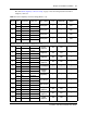
The table RJ-21 telephony connector wiring on page 31 lists the wiring details for the RJ-21
telephony connector.
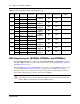
Table 12 RJ-21 telephony connector wiring (Sheet 1 of 2)
Device Pin Connection Wire color Type of device Port Default DN
Default line
number
1
26 Tip White-Blue
Analog line — — 061
1 Ring Blue-White
2
27 Tip White-Orange
Analog line — — 062
2 Ring Orange-White
3
28 Tip White-Green
Analog line — — 063
3 Ring Green-White
4
29 Tip White-Brown
Analog line — — 064
4 Ring Brown-White
Note: The four analog lines are only available on the standard main units; they are not available on the BRI series
(b-series) main units, which have two BRI ports instead.
5
30 Tip White-Slate
Analog
telephone
413 233 —
5 Ring Slate-White
6
31 Tip Red-Blue
Analog
telephone
414 234 —
6 Ring Blue-Red
7
32 Tip Red-Orange
Analog
telephone
415 235 —
7 Ring Orange-Red
8
33 Tip Red-Green
Analog
telephone
416 236 —
8 Ring Green-Red
9
34 No connection Red-Brown
No connection — — —
9 No connection Brown-Red
10
35 Tip Red-Slate
Auxiliary
Ringer
—— —
10 Ring Slate-Red
11
36 Tip Black-Blue
Page Relay — — —
11 Ring Blue-Black
12
37 Tip Black-Orange
Page Output — — —
12 Ring Orange-Black
13
38 Tip Black-Green
Music Source — — —
13 Ring Green-Black
14
39 Tip Black-Brown
Digital
telephone
412 232 —
14 Ring Brown-Black
15
40 Tip Black-Slate
Digital
telephone
411 231 —
15 Ring Slate-Black
16
41 Tip Yellow-Bl ue
Digital
telephone
410 230 —
16 Ring Blue-Yellow