
Technical data


Chapter 2 System overview 17
Installation Checklist and Quick Start Guide
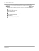
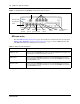
Figure 2 BRI main unit (BCM50be shown) ports and connectors
Expansion units and media bay modules
The BCM50 system includes up to two expansion units. The expansion unit is designed to
accommodate one media bay module (MBM) to connect additional telephony equipment to the
system. The MBMs connect with external devices to implement various trunks and stations.
The table Trunk, station, and combination MBMs on page 17 lists the trunk MBMs and station
MBMs that are supported in the expansion units.
Additional hardware
In addition to the main unit, expansion unit, and MBMs, the BCM50 system includes the
additional hardware listed in the table BCM50 hardware descriptions on page 17.
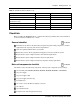
Table 8 Trunk, station, and combination MBMs
Trunk MBMs Station MBMs Combination MBMs
ADID4/ADID8 ASM8/ASM8+ 4x16
BRIM DSM16/DSM16+/DSM32/DSM32+ G4x16/G8x16
DTM GASM
GATM4/GATM8
Table 9 BCM50 hardware descriptions (Sheet 1 of 2)
Hardware Description
Rack-mount shelf A shelf designed for mounting up to four BCM50 units (main unit and expansion unit)
into a standard 19-inch equipment rack. An optional patch field, which provides RJ-45
connectors for all main unit trunk and station interfaces, is available.
Wall-mount bracket A bracket designed for mounting a BCM50 unit (main unit or expansion unit) to a wall.
An optional wiring-field card (WFC), which provides RJ-45 connectors for all main unit
trunk and station interfaces, is available with the wall-mount bracket.
USB
LAN
(port 1)
Expansion/LAN
(port 2, port 3)
WAN Additional LAN
OAM
(port 0)
RJ-21 telephony
connector
Power
Retention-clip
mounting hole
Music
source
Reset
switch
BRI ports
The 4 lines
on the RJ-21
telephony
connector are
not available
with the BRI
ports.