BCM50 Installation Checklist and Quick Start Guide BCM50 Business Communications Manager 5.0 Document Status: Standard Document Number: NN40170-308 Document Version: 03.
Copyright © 2006–2009 Nortel Networks, All Rights Reserved All rights reserved. The information in this document is subject to change without notice. The statements, configurations, technical data, and recommendations in this document are believed to be accurate and reliable, but are presented without express or implied warranty. Users must take full responsibility for their applications of any products specified in this document. The information in this document is proprietary to Nortel Networks.
SOFTWARE LICENSE NORTEL NETWORKS INC. (“NORTEL NETWORKS”) TELECOMMUNICATION PRODUCTS THIS LEGAL DOCUMENT IS A LICENSE AGREEMENT ("License") BETWEEN YOU, THE END-USER ("CUSTOMER") AND NORTEL NETWORKS. PLEASE READ THIS LICENSE CAREFULLY BEFORE USING THE SOFTWARE. BY USING THIS SOFTWARE, YOU, THE CUSTOMER, ARE AGREEING TO BE BOUND BY THE TERMS OF THIS LICENSE.
Except for Java Product (as defined herein below), CUSTOMER may assign collectively its rights under this License to any subsequent owner of the associated hardware, but not otherwise, subject to the payment of the then current license fee for new users, if any.
Copyright 1992 Livingston Enterprises, Inc. Livingston Enterprises, Inc. 6920 Koll Center Parkway Pleasanton, CA 94566 Permission to use, copy, modify, and distribute this software for any purpose and without fee is hereby granted, provided that this copyright and permission notice appear on all copies and supporting documentation, the name of Livingston Enterprises, Inc.
NN40170-308
Contents 7 Contents Chapter 1 Getting started . . . . . . . . . . . . . . . . . . . . . . . . . . . . . . . . . . . . . . . . . . . . . . . . . 9 About this guide . . . . . . . . . . . . . . . . . . . . . . . . . . . . . . . . . . . . . . . . . . . . . . . . . . . . . . . 9 Purpose . . . . . . . . . . . . . . . . . . . . . . . . . . . . . . . . . . . . . . . . . . . . . . . . . . . . . . . . . . 9 Audience . . . . . . . . . . . . . . . . . . . . . . . . . . . . . . . . . . . . . . . . . . . . . . . . . .
Contents BCM50 main unit LAN connection . . . . . . . . . . . . . . . . . . . . . . . . . . . . . . . . . . . . . . . . 37 DHCP server configuration and IP address . . . . . . . . . . . . . . . . . . . . . . . . . . . . . . . . . 37 BCM50 and BCM50b main units (no integrated router) . . . . . . . . . . . . . . . . . . . . 37 BCM50a, BCM50e, BCM50ba, or BCM50be main unit (with integrated router) . . . . . . . . . . . . . . . . . . . . . . . . . . . . . . . . . . . . . . . . . . . . 38 WAN connection . .
Chapter 1 Getting started IMPORTANT! Print this chapter to record the progress of the BCM50 system installation and configuration. Use the tables and checklists to guide you through the installation process. About this guide The Installation Checklist and Quick Start Guide describes how to install and configure Business Communications Manager 50 (BCM50) systems running BCM50 software. Purpose The procedures described in this guide relate to the BCM50 hardware.
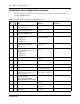
Chapter 1 Getting started Installation and configuration summary The table Installation and configuration checklist on page 10 provides the tasks to install and configure a BCM50 system. Table 1 Installation and configuration checklist (Sheet 1 of 2) ; Task Reference 5 min Review the BCM50 system hardware System overview on page 15 and configuration tools. 2 min Verify that you have the tools, materials, and data required.
Chapter 1 Getting started 11 Table 1 Installation and configuration checklist (Sheet 2 of 2) ; Task Reference Comments 10 min Apply the keycode. Software keycode on page 43 15 min Configure the required BCM50 system parameters (Element Manager or Startup Profile). System parameters on page 43 1 min Configure the MBMs with Element Manager. MBM configuration on page 48 N/A (Optional) Complete the configuration by customizing other parameters.
Chapter 1 Getting started Tools and system information Use the table Tools on page 12 and the table System information on page 12 to record values and comments about tools and system information. Table 4 Tools Description Value Comments Value Comments Laptop (or PC) with: • Windows XP, Windows Vista, Windows Server 2003, Windows Server 2008 or Citrix Presentation Server 4.
Chapter 1 Getting started 13 Table 5 System information (Sheet 2 of 2) Description Value Comments Fractional T1 channel numbers Frame relay DLCI/CIR (if applicable) V.90 modem settings (North America only) SNMP agent (security, version) SNMP manager IP address SNMP community string Checklists Before installing the BCM50 hardware, complete the following checklists. For more information, see the Installation and Maintenance Guide.
Chapter 1 Getting started Expansion unit and media bay modules components checklist 5 minutes (optional) Check that you have the following components, and inspect the components for any damage: F one expansion unit F one expansion unit power supply F one power-supply cable F one expansion cable (shielded Ethernet cable) F one power-supply retention clip F four rubber feet F the correct media bay modules (MBM) NN40170-308
Chapter 2 System overview You require the following hardware components and configuration tools to install and configure your BCM50 system: • • • • • Main units on page 15 Expansion units and media bay modules on page 17 Additional hardware on page 17 Nortel Business Element Manager on page 18 Startup Profile on page 19 For more information, see the chapter “Introducing the BCM50 hardware” in the Installation and Maintenance Guide.
Chapter 2 System overview Figure 1 Standard main unit (BCM50e shown) ports and connectors WAN Additional LAN Retention-clip mounting hole Power OAM (port 0) LAN (port 1) Expansion/LAN (port 2, port 3) Reset switch Music source USB RJ-21 telephony connector BRI main units The table BRI main units descriptions on page 16 describes the standard main units, and the figure BRI main unit (BCM50be shown) ports and connectors on page 17 shows a BRI main unit.
Chapter 2 System overview 17 Figure 2 BRI main unit (BCM50be shown) ports and connectors WAN Additional LAN The 4 lines on the RJ-21 telephony connector are not available with the BRI ports. BRI ports Retention-clip mounting hole Power OAM (port 0) LAN (port 1) Expansion/LAN (port 2, port 3) Reset switch Music source USB RJ-21 telephony connector Expansion units and media bay modules The BCM50 system includes up to two expansion units.
Chapter 2 System overview Table 9 BCM50 hardware descriptions (Sheet 2 of 2) Hardware Description Patch panel The patch panel simplifies the connections of lines and extensions to the main unit. The patch panel installs into the rack-mount shelf in a standard equipment rack and connects to the telephony connector. Wiring-field card (WFC) The WFC simplifies the connections of lines and extensions to the main unit.
Chapter 2 System overview • • • 19 Operating System: Windows XP, Windows Vista, Windows Server 2003, Windows Server 2008, Citrix Presentation Server 4.0 BCM applications for BCM 5.0 support the following Vista versions: Microsoft Vista Business, Windows Vista Ultimate, and Windows Vista Enterprise. Both 32-bit and 64-bit versions of Windows Vista are supported except for the limitations identified in Nortel Business Communications Manager 450—System Overview (NN40170-103).
Chapter 2 System overview NN40170-308
Chapter 3 Hardware installation See the following procedures to install the BCM50 hardware: • • • • • • • • • • • Main unit and expansion unit installation on page 21 Media bay module installation on page 27 Expansion unit installation on page 29 Power-supply connection on page 30 Telephony connector on page 30 BRI integrated ports (BCM50b, BCM50ba, and BCM50be) on page 32 MBM wiring on page 34 BCM50 main unit LAN connection on page 37 DHCP server configuration and IP address on page 37 WAN connection
Chapter 3 Hardware installation Use the following procedures to install a BCM50 unit in a rack: • • To install the rack-mount shelf in an equipment rack on page 22 To install a BCM50 unit on the rack-mount shelf on page 22 To install the rack-mount shelf in an equipment rack 5 minutes 1 Determine the location in the rack where you want to install the BCM50 unit. 2 Position the rack-mount shelf in the rack. 3 Align the holes in the rack-mount shelf with the holes in the equipment rack rails.
Chapter 3 Hardware installation 5 23 Install the power supply using a method appropriate for your installation. For details about installation options, see Installing the BCM50 power supply on page 26. To install a BCM50 unit on top of another unit 2 minutes Warning: For safety reasons, do not stack more than one unit on top of a first BCM50 unit. 1 Insert the power-supply retention clip into the BCM50 unit. 2 Place the BCM50 unit on top of the first unit.
Chapter 3 Hardware installation To install the BCM50 wall-mount bracket 6 minutes 1 Optional: Mount a plywood backboard securely to the wall. Use a ruler and a level to level the plywood backboard. 2 Place the wall-mount bracket on the backboard or wall, and mark the location of the center keyhole-shaped screw hole on the plywood backboard. See the figure Wall-mount bracket on page 24.
Chapter 3 Hardware installation To install a BCM50 unit on the wall-mount bracket 25 6 minutes 1 Insert the power-supply retention clip into the BCM50 unit. 2 Slide the wall-mount lock fully to the right (unlock position). See the figure Wall-mount lock in unlock position on page 25. Figure 5 Wall-mount lock in unlock position 3 Align the feet on the BCM50 unit with the four holes in the wall-mount bracket.
Chapter 3 Hardware installation Figure 6 Slide in the WFC 4 Press the WFC firmly at the top-left corner, center, and right tabs. The WFC snaps into place. 5 Optional: Install the three screws to secure the WFC in place. Desktop-mount installation Follow this procedure to install a BCM unit (main unit or expansion unit) on a desktop or other flat surface. To install a BCM50 unit on a desktop or flat surface 4 minutes 1 Insert the power-supply retention clip into the BCM50 unit.
Chapter 3 Hardware installation To install the power supply on the rack-mount shelf 1 27 2 minutes Place the power supply behind the BCM50 unit on the back of the rack-mount shelf. Ensure the power supply is on its side with the label facing the back of the shelf. 2 Use two cable ties to secure the power supply to the rack-mount shelf. 3 Repeat steps 1 and 2 for each power supply you mount.
Chapter 3 Hardware installation To verify the MBM switches 2 minutes 1 Verify that the 6-pin dip switch is set to on for all MBMs that have the 6-pin dip switch. 2 To install a global analog trunk module (GATM): 3 a For the dip switches on the left side, at the rear of the module, set all the switches to on. b For the dip switches on the right side, at the rear of the module (country profile switches), set all the switches to off. The GATM automatically downloads the country profiles.
Chapter 3 Hardware installation 3 29 Push the MBM completely into the expansion unit. You hear a click when the MBM is firmly seated in the expansion unit. The MBM must be configured for it to function. For information about configuring an MBM, see To configure the MBMs on page 48. Expansion unit installation After installing an MBM in the expansion unit, install one or two expansion units in the same manner as the main unit (in a rack, on a wall, or on a flat surface).
Chapter 3 Hardware installation Power-supply connection Use the power supply and power-supply cable supplied with each BCM50 unit. Connect the power supply to your BCM50 system by one of the following methods: • • To connect the power supply without a UPS on page 30 “To connect the power supply using a UPS” – refer to the Installation and Maintenance Guide. For more information, see the chapter “Connecting the cables to the BCM50 system” in the Installation and Maintenance Guide.
Chapter 3 Hardware installation 31 The table RJ-21 telephony connector wiring on page 31 lists the wiring details for the RJ-21 telephony connector.
Chapter 3 Hardware installation Table 12 RJ-21 telephony connector wiring (Sheet 2 of 2) Device 17 18 19 20 21 22 23 24 25 Pin Connection Wire color Type of device Port Default DN Default line number Digital telephone 409 229 — Digital telephone 408 228 — Digital telephone 407 227 — Digital telephone 406 226 — Digital telephone 405 225 — Digital telephone 404 224 — Digital telephone 403 223 — Digital telephone 402 222 — Digital telephone 401 221 — 42
Chapter 3 Hardware installation 33 Figure 8 BRI ports and pin out (BCM50b shown) BRI ports BRI port pin out The table BRI port wiring on page 33 and the table BRI line numbering on page 33 list the wiring details for the RJ-45 ports.
Chapter 3 Hardware installation MBM wiring 15 minutes Telephone lines connect to the expansion unit through the connectors on the MBM. For more information, see the chapter “Connecting the cables to the BCM50 system” in the Installation and Maintenance Guide. Danger: Electrical shock hazards Electrical shock hazards from the telecommunications network and ac mains are possible with this equipment.
Chapter 3 Hardware installation 35 Warning: Use only qualified persons to service the system. The installation and service of this unit must be performed by service personnel with the appropriate training and experience. Service personnel must be aware of the hazards of working with telephony equipment and wiring. They must be experienced in techniques that minimize any danger of shock or equipment damage.
Chapter 3 Hardware installation • If your system includes another expansion unit, repeat this procedure to add more telephone lines or proceed to Connect extensions to the expansion unit on page 36 to add extensions. To connect analog telephone lines to the GATM4, GATM8, G4x16, or G8x16 1 Obtain a 25-pair cable with an RJ-21 connector on one end. 2 Plug the RJ-21 connector of the cable into the RJ-21 connector on the front of the MBM.
Chapter 3 Hardware installation 37 BCM50 main unit LAN connection For more information, see the chapter “Connecting the BCM50 system to the LAN and WAN” in the Installation and Maintenance Guide. Warning: The DHCP server on the main unit is enabled (IP Phones only) by default. If your network already contains a DHCP server, then disable the DHCP server on the main unit. To connect a BCM50 system to the LAN 5 minutes 1 Connect one end of a standard Ethernet cable to your LAN.
Chapter 3 Hardware installation If an external DHCP server is not present If an external DHCP server is not present, then the main unit uses the following default IP configuration: IP address: 192.168.1.2 Subnet mask: 255.255.255.0 Gateway: 192.168.1.1 The DHCP server on the main unit supplies IP configuration information for all IP devices (PCs and IP Phones). It also supplies specific connection information to the IP Phones.
Chapter 3 Hardware installation 39 If you select the standard DHCP server on the main unit, you must first disable the DHCP server on the integrated router. You can then configure the DHCP server functionality in the same way as a nonrouter version. If you select the DHCP server on the integrated router you can configure the router using the router WebGUI tool. By default, the integrated router LAN IP address is 192.168.1.
Chapter 3 Hardware installation 4 Plug the other end of the telephone cable into the WAN port. Note: To use the ADSL line for both ADSL and regular voice communication, you must install a splitter filter, which is provided by your service provider. To connect the BCM50e or BCM50be to the WAN 2 minutes 1 Use the Integrated Router Web GUI to configure the router card on the BCM50e or BCM50be main units.
Chapter 4 System configuration The initial configuration defines your BCM50 system to the network. It also gives the system a unique identity and initial parameters. Then you can continue with the specific configurations for your system.
Chapter 4 System configuration BCM Web page downloads After you connect your computer to the BCM50 system, either through the OAM port or through a LAN connection, download Element Manager from the Administrator Applications area of the BCM Web page. You can use the latest Element Manager version (for BCM50 Release 5.0) to manage all previous BCM systems that require Element Manager (BCM50 Release 3.0, BCM450 1.0 and BCM450 5.0, and BCM 4.0).
Chapter 4 System configuration 3 43 On the Administrator Applications page, click Startup Profile template. The Startup Profile template panel appears. 4 Read the information on this panel. 5 Click Download Startup Profile template on the right side of the screen, and follow the instructions to download. Software keycode You require a keycode to enable software features on your BCM50 system. You receive only one keycode whether you purchase one feature or a bundle of features.
Chapter 4 System configuration Table 15 BCM50 system parameters (Sheet 2 of 3) Parameters Element Manager Modem: • Enable/disable modem Configuration > Resources Modem > Dial Up Interfaces Feature 9*8 > Modem System: • Region Administration > Utilities > Reset > Cold Reset Telephony Services System Feature **PROFILE Telephony startup: • Template • Start DN Administration > Utilities > Reset > Cold Reset Telephony Services Telephony Startup Feature **STARTUP Voice mail: • Attendant DN • UI
Chapter 4 System configuration 45 Table 15 BCM50 system parameters (Sheet 3 of 3) Parameters Element Manager Startup Profile Telset Administration IP Phones: • Enable registration • Enable global pwd • Global pwd • Auto-assign DNs • Advertisement logo Configuration > Resources IP Telephones > Telephony Resources SNMP Agent: • Enable/disable SNMP agent • Minimum security • SNMP version support Configuration > Administrator Access > SNMP > General tab SNMP Agent N/A SNMP community: • Community str
Chapter 4 System configuration To configure the system using the Startup Profile (optional) 15 minutes Note: The Startup Profile template uses macros to perform certain functions. You must set your Excel macro security level to medium or low to enable the macros: • From the Tools menu, select Macros and then select Security. • Select Medium or Low. • Exit from Excel. • Open the Startup Profile template (in Excel). • Enable macros if prompted.
Chapter 4 System configuration 9 47 Insert the USB storage device into the USB port of the computer. 10 Copy the Startup Profile (.sps file) to the root directory of the USB storage device. 11 If you want to load your keycode using the Startup Profile, copy the keycode file to the root directory of the USB storage device. The name of the keycode file on the USB storage device must exactly match the filename you entered in the Startup Profile editor.
Chapter 4 System configuration For information about using the router WebGUI tool, see the Integrated Router Configuration Guide for your product. 5 Configure the attributes for your system. MBM configuration You must configure the MBMs to function with your BCM50 system. For more information, see the chapter “Completing the initial installation (optional)” in the Installation and Maintenance Guide. To configure the MBMs 1 minute/MBM 1 Open Element Manager and connect to your BCM50 system.
Chapter 4 System configuration 9 49 If you installed a second expansion unit, repeat steps 4 to 7 to enable the second MBM. You can set other parameters for the MBMs depending on the type of MBM you installed.
Chapter 4 System configuration NN40170-308