
Instruction manual


Strata DK40i
Station and Line Capacities
Strata DK General Description 6/00 13
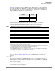
Table 5 shows maximum capacity for a DK40i system. DKi Quote, an auto quote program that
runs on a PC with Microsoft® Windows®, is available from Toshiba to generate DK40i quotes
and configurations. Also, refer to the Strata DK Installation and Maintenance (I&M) Manual,
Chapter 2 – DK40i Configuration, for more information.
Table 5 Maximum CO Lines/Ports and BRI Line and Station Circuits
Attaining maximum system capacities depends on power consumption of a particular
configuration (see Table 6). Power factor calculations in accordance with the Strata DK I&M
Manual will determine if the maximum capacities in these tables can be reached.
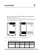
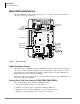
The DK40i Base and Expansion cabinets provide an extensive number of features for a telephone
system of its size. See Table 40 on Page 109 for a list of DK40i, Release 4.3 features and
capacities.
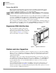
ISDN BRI Lines
Stations can be a combination of ISDN TE-1 and TA S-type devices and digital, electronic or
standard telephones. CO line combinations include ground or loop start, DID, Tie or ISDN BRI.
Each BRI line circuit uses up two CO lines at system capacity. All other line circuits use up one
CO line of system capacity.
Each BRI station circuit uses up to two station ports of system capacity. All other station circuits
use up one station port of system capacity.
Hardware
Maximum
Allowed
CO Lines 12
Station Ports 28
BRI Line Circuits 6
BRI Station Circuits 10
Table 6 DK40i Station and Line Capacities and Universal Printed Circuit Board Slots
Lines and PCB Slots DK40i
Universal slots
1
1. There are four universal slots in the DK40i expansion unit.
4
1
Stations
2
2. Line and station capacities cannot exceed 28 stations and/or 12 CO lines. Incremental capacities depend on the type
of station/line PCBs installed. All increments are not available with all PCB types.
8~28
2
CO lines – loop start 0, 2, 4, 8 or 12
3
3. Increments vary and depend on the type of line PCBs installed.
CO lines – ground start 0, 2, 4, 8 or 12
3
DID lines (analog)
4
4. In the D40i, DID and Tie, lines do not use up station ports as in DK40, R3.1 and the DK424 R3.2. Each BRI line
circuit uses up to two CO lines of system capacity and no station ports.
0, 2, 4, 8 or 12
3
Tie lines (analog)
3
0, 2, 4, 8 or 12
3
T1 lines 8 or 12 channels/lines
ISDN BRI line circuits (S/T type and/or U type)
5
5. Each S/T type circuit requires an NT-1 device when connected to a Central Office BRI line circuit.
2, 4 or 6 circuits (12 B-channels/lines)
3
ISDN PRI line circuits 8 or 12 channels/lines
Squared System Maximum (ground/loop lines + stations) 12 lines + 12 stations
Squared System Maximum (Tie/DID lines + stations) 12 lines + 12 stations