
User's Manual


DW-SBTM1_UM_00.doc
Stand-alone Bluetooth Module User Manual
Page 5
General Description:
NOTE: All references to internal parts are to be
crosschecked against BOM as they represent confidential
information.
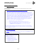
DW-SBTM1 is a standalone Bluetooth module running
HCI level Bluetooth stack. It enables data connectivity
over distances as much as 10m (30ft). The HCI interface
is standard to ###FLASH or ###ROM parts (check BOM).
DW-SBTM1F = uses ###Flash part (check BOM)
DW-SBTM1R = uses ###ROM part (check BOM)
The integrated circuit includes both the RF processor as well as the baseband (BB)
processor. All the related Bluetooth protocols that deal with RF modulation, channel
hoping sequence and timing, are dealt within the chip. It also has an internal regulator
for the core and RF circuitry, and internal VCO and PLL filter.
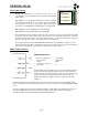
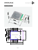
The module consists of the ###ROM/###FLASH chip (check BOM), a 10ppm crystal,
antenna balloon and filter, and permanently attached antenna (see picture and internal
schematic). A RF shield covers all the components, except antenna.
Module UART Interface:
UART Specifications:
Power-on baud rate: 115200bps
Flow control: RTS/CTS
Parity: None
Number of stop bits: 1
Data bits: 8
For the Flash based module the set-up of the UART interface
has to be done through the SPI port, as part of the general
module set-up. For production, the setup is done at the same
time as the general programming of the module. For the
ROM based module, UART is set-up at power-on through
jumpers
NOTE: UART port has standard logic levels. It can connect directly to a CPU/MPU UART
port, but it needs an external level translator in order to connect to standard RS232 COMM
ports.
Levels on UART pins are between GND and VDD1. UART_RTS, and UART_CTS are active
low. The UART port buffer is used for both sending payload data and controlling the
module. Payload data is embedded in standard HCI protocol.
FCC:
R37-DWSBTM1
IC:###-DWSBTM1
BT:###-DWSBTM1