
Manual


USB WIRELESS BRIDGE USER’S MANAUL REV. 02 5
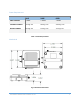
The mechanical dimensions for the Wireless Bridge are shown in Figure 1. The mechanical dimensions
are shown with the optional DIN rail mount bracket which is not included with the standard part
number. Mechanical data for the antenna is not shown.
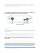
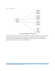
Pinout and Wiring
The pinout follows a standard Micro USB device. The device does not self-power from the USB port. The
supply voltage must be injected on the power connector to power the device.
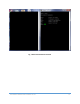
Fig. 2 Connector Diagram
Operation
Standard Operation
The USB Wireless Bridge is designed to be data transparent. By default, any data sent into one device is
broadcast and received by all other Wireless Bridge devices within range. Any device that receives the
transmitted data packet will send the received data out the data port to its host. Without any
configuration the Wireless Bridge will operate in a point-to-point or point-to-multipoint mode.
Additional addressing can be used to isolate communication between specific devices or to create
unique networks.
When the micro USB connector is plugged into a USB host device such as a computer, the Wireless
Bridge enumerates as two standard serial COM ports. One port is a data port and can send and receive
data. The second COM port is the device’s information port.
The Wireless Bridge uses standard composite device drivers which are preinstalled in Windows 10 and
MAC computers. Drivers will need to be installed for Windows 7 machines. While not every machine will
enumerate exactly the same, as a general rule the lower numbered COM port is for Wireless Bridge