USB Wireless Bridge USERS MANUAL R02
Contents Overview ....................................................................................................................................................... 3 Specifications ................................................................................................................................................ 3 Performance ............................................................................................................................................. 3 Power Requirements ...
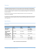
Overview The USB Wireless Bridge is designed to work with one of the other Datawave Wireless Bridge devices. The USB Wireless Bridge enumerates as a multiple COM port device and emulates a standard COM port for data. The USB wireless bridge is typically used with an RS-232, RS-485, ADIO Wireless Bridge or with stand-alone Digi XBee modules. In a typical use case, the USB Wireless Bridge acts as a data collector for one of these devices.
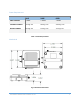
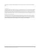
Power Requirements 24LP 24HP 09SX INPUT VOLTAGE 7-30VDC 7-30VDC 7-30VDC TRANSMIT CURRENT 12mA @ 12V 40mA @ 12V 270mA @ 12V RECEIVE CURRENT 12mA @ 12V 12mA @ 12V 17mA @ 12V Table 2. Power Requirements Mechanical Fig. 1 Mechanical Dimensions USB WIRELESS BRIDGE USER’S MANAUL REV.
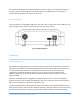
The mechanical dimensions for the Wireless Bridge are shown in Figure 1. The mechanical dimensions are shown with the optional DIN rail mount bracket which is not included with the standard part number. Mechanical data for the antenna is not shown. Pinout and Wiring The pinout follows a standard Micro USB device. The device does not self-power from the USB port. The supply voltage must be injected on the power connector to power the device. Fig.
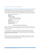
configuration. The higher numbered COM port can be used to transmit or receive data over the USB port. LED Indication The wireless bridge has four LEDS for indication. The Blue Power LED is lit any time the Wireless Bridge is properly powered. A green TX LED and yellow RX LEDs indicate activity on the serial port of the device. They do not necessarily reflect all activity that may be occurring over the air as they will only blink when a properly addressed data packet is received.
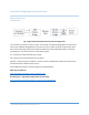
Common Configurations and Use Cases Radio Architectures Point-to Point Fig. 4 Typical USB to Serial Device Point-to-Point Configuration The most basic architecture is point-to-point. In this mode, one Wireless Bridge Device communicates with a second Wireless Bridge Device. If more than one pair of radios are within range of each other, then certain addressing commands should be set within the on board Digi XBee radio to isolate the individual pairs.
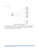
Point-to-Multipoint Fig. 5 Point-to-Multipoint Configuration Figure 5 shows a typical point-to-multipoint configuration. By default, all the Wireless Bridge devices will broadcast their data meaning that point-to-multipoint mode will work without any configuration. If there is the potential for other Wireless Bridge networks to be in the same area, then all devices in a given network may want to be set to a non-default PAN ID. USB WIRELESS BRIDGE USER’S MANAUL REV.
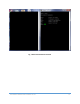
Communicating with the Wireless Bridge The Wireless Bridge device can be connected to a PC through the micro USB port. Figure 6 shows the device manager view of an example connected device. Note that a single device shows up as two separate COM ports. In Figure 6, the COM ports are COM43 & COM44. The COM port numbers will vary from machine to machine depending on what COM port device drivers have been previously installed. Fig.
Fig. 7 Data and Information Terminals USB WIRELESS BRIDGE USER’S MANAUL REV.
USB Command Reference Table Main command Function Command Name help info set & get defaults pkts.en Command Description Displays list of main commands Displays device serial number Restores factory default settings. Enables JSON output format when used with an ADIO Wireless Bridge Value Range NA No parameters NA No parameters NA No parameters 0 0 or 1 Stores settings to nonNA volatile memory. Displays loaded firmware NA version Fig 8.
Fig. 9 Terminal Session Command Example Configuring the XBee Module The USB Wireless Bridge utilizes the Digi XBee module. Consequently, all radio settings can be read or set with Digi AT commands or Digi X-CTU software. As a general rule the only commands that might need be set are the Networking commands. Any I/O commands or other features are not used. See Digi’s website at www.digi.com and the XBee user manual and discussion forums for more information.
Part Numbers and Compatibility The USB Wireless Bridge comes with three basic options depending on range requirements. The 24LP and 24HP operate at 2.4 GHz and the 09SX operates in the 902-928MHz band. Any 24xx device can transmit and receive data from an 24xx RS-485, USB or ADIO Wireless Bridge. Likewise for the 09SX families. Orderable Part Numbers Description WB-USB-24LP-A 2.4 GHz 6.3mW Wireless Bridge USB WB-USB-24HP-A 2.
Certifications United States (FCC) The Datawave Wireless Bridges comply with Part 15 of the FCC rules and regulations. Compliance with the labeling requirements, FCC notices and antenna usage guidelines is required. FCC notices IMPORTANT: The RF device has been certified for remote and base radio applications. This equipment has been tested and found to comply with the limits for a Class B digital device, pursuant to Part 15 of the FCC Rules.